Definitely learning on this project Patrick, certainly the most intricate and careful build I have undertaken so far, not for the faint hearted.
Just waiting for a few things from Farnell and we are go for test launch")
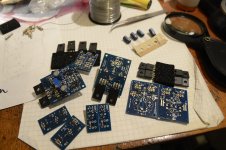
Very lucky with matching output BJTs, found enough well matched Sankens out of 30 each for both SLHP sets plus regs and two sets of JLH boards. I even went the distance and matched the LM329s.
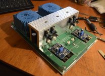
A pic to keep the thread interesting, the Sankens are just tacked in while I wait to look at mounting distance with CSS boards. You might notice a couple components from the servo circuit were added by mistake whilst I was in the SMD rabbit hole...
Just waiting for a few things from Farnell and we are go for test launch
Very lucky with matching output BJTs, found enough well matched Sankens out of 30 each for both SLHP sets plus regs and two sets of JLH boards. I even went the distance and matched the LM329s.
A pic to keep the thread interesting, the Sankens are just tacked in while I wait to look at mounting distance with CSS boards. You might notice a couple components from the servo circuit were added by mistake whilst I was in the SMD rabbit hole...
Attachments
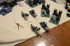
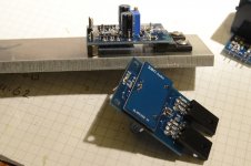
Well dammit, tested the regs and we have both positive at 14.60V and both negative at 16.70V.
That is mental, they should be very close however both polarity's are exactly even respectively.
Patrick - does increasing R1 resistance reduce Vout? I need to drop 2V on the negative regs.
That is mental, they should be very close however both polarity's are exactly even respectively.
Patrick - does increasing R1 resistance reduce Vout? I need to drop 2V on the negative regs.
Last edited:
You should first find out what has gone wrong, because the circuits are exactly symmetrical and you should not get different voltages.
First thing is to make sure you have the correct input / output / Gnd pin assignment.
They follow 78xx / 79xx regulators and hence are different between N & P.
See datasheet of 78xx / 79xx.
Patrick
First thing is to make sure you have the correct input / output / Gnd pin assignment.
They follow 78xx / 79xx regulators and hence are different between N & P.
See datasheet of 78xx / 79xx.
Patrick
No Patrick, I needed to step away, have some food and calibrate with coffee.
I didn't swap the Gnd shorting link between -/+ on my power supply outputs, the neg was tied to gnd. Remember I am an idiot here...
All good my friend, these regs are excellent. When I saw the boards first I thought what the @**k is he doing to us?! But I love the super compact design now. They are useful for a million little things, like a supply for the Muses Volume control kit.
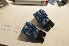
Anyway, we have:
pos reg #1: +14.59V
pos reg #2: +14.62V
neg reg#1: -14.59V
neg reg#2 -14.60V
Brilliant stuff. The CSS boards are finished and mounted so will drill some holes in metal later and get things mounted up.
Found an old pair of SuperTeddyRegs maybe six years old, still have another pair of each bare boards. They were very good in their day but hard to build up right. These need a tweak for 15V so may try them out at some point.
I didn't swap the Gnd shorting link between -/+ on my power supply outputs, the neg was tied to gnd. Remember I am an idiot here...
All good my friend, these regs are excellent. When I saw the boards first I thought what the @**k is he doing to us?! But I love the super compact design now. They are useful for a million little things, like a supply for the Muses Volume control kit.
Anyway, we have:
pos reg #1: +14.59V
pos reg #2: +14.62V
neg reg#1: -14.59V
neg reg#2 -14.60V
Brilliant stuff. The CSS boards are finished and mounted so will drill some holes in metal later and get things mounted up.
Found an old pair of SuperTeddyRegs maybe six years old, still have another pair of each bare boards. They were very good in their day but hard to build up right. These need a tweak for 15V so may try them out at some point.
Attachments
Those regulators have been built umteen times and with different voltages and current limits.
Like all other projects from us, they have been thoroughly tested, by us and by Beta testers, before release, so as to ensure they work and are bug free.
If they don't then it is most likely something very trivial, as in this case.
Patrick
Like all other projects from us, they have been thoroughly tested, by us and by Beta testers, before release, so as to ensure they work and are bug free.
If they don't then it is most likely something very trivial, as in this case.
Patrick
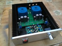
Nearly there folks. The Xen motherboard from SB is very neat. 25VA per channel, CREE diodes, all good.
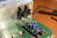
Now I have to say the SHPP board was very difficult for me with the listed parts, the pads are incredibly tight around the op amp so will get smaller parts in and try again. I'm just not happy with my work on the board right now. A pic below shows the mess, shameful... I'm worried about fussing too much and overheating.
For anybody about to start their build, I highly recommend heeding the advice in the PDF regarding smaller case sizes for the SHPP, especially for C1,2,11,12 - 1206, 10Uf 25V, change to 0805 package. All 0805 resistors could do with 0603 if you can manage the smaller size.
On the other hand the Xfeed board is a nice little assembly. Looking forward to hearing how it performs. Unfortunately I had to connect the circuit permanently on, so will bypass at the pot pins if needed.
Attachments
Last edited:
If there is demand we shall offer a revised version of our original motherboard with improved layout.
2mm boards with cutout, so will not be entirely cheap.
But a through-hole passive XFD is included on board.
SHPP not, as it will then be impossible to solder.
The trick to solder the SHPP is to start from the moddle and work outwards.
Use solder iorn to meld a tiny bit of solder on one pad, and then shift in the part sideways to push away the iron tip.
Then just heat and let solder suck in on the other end.
Use 0.35mm low-temperature solders (mine has 4% silver).
I just use 40x40x2mm angle and connect them thermally to the side heaatsinks of the 2107 case.
Patrick
Looking good! I'm happy that I got me a pair of SB's motherboards too for up-coming projects. What are the measurements of your aluminum angle? 60*40*6mm? I'm thinking of ordering some from eBay...
Sorry Martti, just seen this.
the angle was from here, 50.8mm x 38.1mm x 6.35mm (2" x 1 1/2" x 1/4")
2" x 1 1/2" Aluminium Angle | 1/4" | Metals4u
It is a little too tall but you need to clear the 35mm caps. Patricks method like his F5-HA is a good one
http://xen-audio.com/documents/f5ha/F5-HA Description V1.4.pdf
I have been asked again for Super Linear boards, including motherboards.
If there is sufficient interest, we'll offer a third run.
See :
https://www.diyaudio.com/forums/gro...r-linear-headphone-amplifier.html#post5579494
Thank you for your interest,
Patrick
If there is sufficient interest, we'll offer a third run.
See :
https://www.diyaudio.com/forums/gro...r-linear-headphone-amplifier.html#post5579494
Thank you for your interest,
Patrick
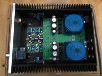
OK we're back, firstly apologies to Patrick for my painfully slow building skills. I realise it's no skin off your nose Patrick but you like to see progress with your designs and it helps to confirm the validity of the whole Xen methodology. Massive respect to those who just get it done.
It's always the final enclosure that stalls me, I'm OCD (in a useful way usually) and certainly for this project I really needed to do Patrick's cracking little design justice. Initially I had this assembled in a makeshift case but the wiring and layout was very awkward - Signal and power cable routing is vital, as I have learned from this forum. And DIY hero's like Stixx and Patrick set the bar high, so we try and do the same as best we can. Not every one can build like Stixx unfortunately
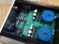
So we are at this point, looking much better in a nice chassis. More room and a sensible layout using Algar's excellent Supply board - again I made last minute decisions, after carefully cutting out the holes for the SLHPA modules, I decided to just use the back end giving more room at the business end.
Now I confess to damaging one regulator while testing again, then another by dropping on the floor and running over it with my desk chair wheel. It was a bad moment, I nearly lost my god damned mind. They were perfectly matched and built and it would be awkward to rematch and build two more as certain MELF low R values were out of stock and I had no more...
No matter. Out came my stash of SuperTeddyReg boards and I quickly built four lovely little regs that work perfectly. I have a bit of experience with these and they do seem to work very well. We shall see and hear the effect soon, but they will do the job for sure.
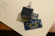
I'm also waiting for T-bar aluminium to mount the regs on in the middle, you can see how it will go but tonight I will install the primary signal wires to the amp boards first and look at routing. Everything need triple checking and careful thought. Double check output offset etc... Also need to build up another SHPP. Much better this time. I lost the M8 nut for the Alps pot... so ordered more and I need to figure the power switch on the back panel.
Without trying state the bleeding obvious it will go like this:
RCA input >> Xfeed >> amp input >> output >> SHPP >>Headphone output >> Nirvana!
Massive tip for those just starting or about to start one day - use the bare PCB's to mark your drill hole positions. Do not wait, like I have done in the past, until after the components are soldered. Before any assembly, consider your layout carefully for this project. Take your time, the boards are small and delicate and hard to get to.
Back very soon I promise
It's always the final enclosure that stalls me, I'm OCD (in a useful way usually) and certainly for this project I really needed to do Patrick's cracking little design justice. Initially I had this assembled in a makeshift case but the wiring and layout was very awkward - Signal and power cable routing is vital, as I have learned from this forum. And DIY hero's like Stixx and Patrick set the bar high, so we try and do the same as best we can. Not every one can build like Stixx unfortunately
So we are at this point, looking much better in a nice chassis. More room and a sensible layout using Algar's excellent Supply board - again I made last minute decisions, after carefully cutting out the holes for the SLHPA modules, I decided to just use the back end giving more room at the business end.
Now I confess to damaging one regulator while testing again, then another by dropping on the floor and running over it with my desk chair wheel. It was a bad moment, I nearly lost my god damned mind. They were perfectly matched and built and it would be awkward to rematch and build two more as certain MELF low R values were out of stock and I had no more...
No matter. Out came my stash of SuperTeddyReg boards and I quickly built four lovely little regs that work perfectly. I have a bit of experience with these and they do seem to work very well. We shall see and hear the effect soon, but they will do the job for sure.
I'm also waiting for T-bar aluminium to mount the regs on in the middle, you can see how it will go but tonight I will install the primary signal wires to the amp boards first and look at routing. Everything need triple checking and careful thought. Double check output offset etc... Also need to build up another SHPP. Much better this time. I lost the M8 nut for the Alps pot... so ordered more and I need to figure the power switch on the back panel.
Without trying state the bleeding obvious it will go like this:
RCA input >> Xfeed >> amp input >> output >> SHPP >>Headphone output >> Nirvana!
Massive tip for those just starting or about to start one day - use the bare PCB's to mark your drill hole positions. Do not wait, like I have done in the past, until after the components are soldered. Before any assembly, consider your layout carefully for this project. Take your time, the boards are small and delicate and hard to get to.
Back very soon I promise
Attachments
Last edited:
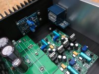
Nice build. Clean and tidy.
But if I may, you have wires running from X'feed and output to both amps on heatsinks.
They (especially input signal wires which are high impedance from the pot) inevitably have to run over your regulators.
I personally would much rather have the amp PCBs on the bottom plate, close to the X'feed PCB.
And have the regulators out of the way on the heat sinks (in your layout).
But by all means try it out as is first and see if it is noise free enough.
Cheers,
Patrick
- Home
- Amplifiers
- Headphone Systems
- The Pioneer Super Linear Circuit