Yesterday I populated the regulator boards and I measured the output voltages with no load while feeding the input with two 9 V batteries in series. I got the following results:
+Vout1 = 14.99 V
+Vout2 = 14.97 V
-Vout1 = -15.05 V
-Vout2 = -14.95 V
I suppose these values are good enough so I don't need to adjust the voltages with R1?
+Vout1 = 14.99 V
+Vout2 = 14.97 V
-Vout1 = -15.05 V
-Vout2 = -14.95 V
I suppose these values are good enough so I don't need to adjust the voltages with R1?

A couple of question about the power supply...
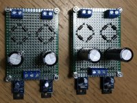
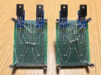
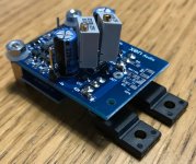
I finished my PSU setup (see attachments) with schottky diodes in a dual bridge rectifier form followed by a 3300 uF Nichicon HW(M) 25 V capacitor per polarity and the Xen discrete regulator board. I have 2 x (25 VA / 2 x 15 V) toroidal trafos => one per channel feeding the PSUs. The question is: when not loading the PSUs I get +/- 14,99 V, but when I attach a load of 150 mA with 100 ohm resistors I get + 14,6 / 14,7 V and -14,9 / -14,8 V. Is this too much of a difference between pos./neg. if I consider a situation with no servo and CCS boards attached? How should I adjust the value of R1 to even out the voltages?
I’m preparing to build my test setup now with roughly matched devices but PSU setup will be the same for my final build with better matched BJTs.
Attachments
Last edited:
The first thing I would check is whether the voltage drop at load comes from the regulators.
(They do have a small output impedance.)
It may well be that the drop comes from upstream, i.e. you do not have enough drop out voltage after the transformers.
You can easily test this with a regulated lab supply set at say +/-19V supplying the regulators directly.
In principle, if you do not use servo and also not CCS, then you will see the difference between rail voltages almost 1:1 at the output.
This you can trim out by adjusting the values of R9 or R10.
You can easily see their effect by changing their values in the Spice files.
Patrick
The voltages after the capacitors were +-/20,3 V with the 150 mA load so I suppose the voltage drop comes from the regulators? Yes, I’ll need to check the Spice files for the regs to adjust accordingly. Maybe it was the post #10? I’m away from the PC now so I can’t check the .asc file...
Edit: Oh and I meant that I will use the CCS boards but not the servo.
Edit: Oh and I meant that I will use the CCS boards but not the servo.
Last edited:
Someone who just finished his build reported marginal stability problems with the JFET input buffer when used in combination with a zero-ohm signal source.
The boards were tested with lab supplies, and not enclosed in a case.
So there might be some RF pickup at the input.
The "problem" was solved by increasing the gate resistors Rg1,2 to ~200R (Susumu 0603).
I did not experience such problem in my own build, as even a 10k pot would have some residual resistance.
And most analog source would have an output impedance of ~50R even if you do not use a pot in between.
So the effective input resistance will always be >=150R, and it is not a problem in real practice.
If you wish to be on the safe side, and already ordered 100R for Rg1, 2, just add a 100R resistor in series with the input pin during test.
And (if you wish to be perfect cosmetically) replace Rg with 220R later.
If you are using the CCS bias (as recommended), I also suggest you test the amplifier without DC servo first.
You might well find that the DC offset is so stable that you would not need the servo at all.
Patrick
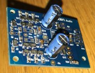
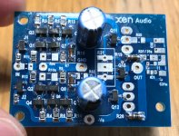
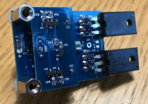
I’ve managed to build up one PSL HPA board and do some testing with it. The bias is adjusted to approx. 150 mA and the DC offset on the output is 61 mV. How should I adjust the CCS board’s R42/R44 resistors to even out the offset? Is it possible to calculate the adjusting resistor value?
Attachments
Last edited:
It is of course possible to calculate.
This is why I never use trimmers, as I always calculate.
If you measure the voltage across R42 and R44 as is, you can determine the bias current of the top and bottom half of the frontend, as is.
R44 determines the top half, and R42 the bottom.
Since it is basically a current conveyor circuit, the difference in bias x R_iv (~10k) equals DC offset.
By lowering the appropriate R (42 for a now +ve offset) by the right amount, you can increase the bias of the appropriate half, and hence trim the offset.
So let's assume you have a DC of +50mV, and voltage across R42 equals 1.5V.
You will need to increase bias of the lower half by (50mV/10k) = 5µA.
The resistor you need to add to R42 in parallel would then be 1.5V/5µA = 300k.
QED.
Understand it for yourself. Don't just follow my word blindly.
Patrick
A small mistake in post #98 :
R_iv should be 5.1k and not 10k.
Hence in the example, the trim resistor should be 150k instead.
Also I forgot to mention :
On the PCB, the permanent resistors R21,22 for the Vbe multiplier are meant to be fixed resistors (0805) of course.
BUT when you are trimming, you can just use a box standard Bourns 3296W 10k linear trimmer.
In fact, if you do not want to replace with fix resistors, you can just leave it in permanently.
That is why there are 3 holes and a white rectangle on the PCB which fits the 3296 exactly.
Patrick
- Home
- Amplifiers
- Headphone Systems
- The Pioneer Super Linear Circuit