I have been listening to the diamond buffer version of the amp in the past 2 days, and it sounds very nice - a neutral, natural kind of sound ") , that keeps me listening for long hours.
, that keeps me listening for long hours.
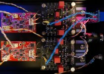
I use TO92 devices as I have them in my parts bin, but soldering SMD is easier than many would expect - it actually took me less time to solder the SMD power supplies in the picture than the amp boards, the trick is to have a good magnifying glass.
, that keeps me listening for long hours.I use TO92 devices as I have them in my parts bin, but soldering SMD is easier than many would expect - it actually took me less time to solder the SMD power supplies in the picture than the amp boards, the trick is to have a good magnifying glass.
Attachments
I received a PM today from a respected member about adding a JFET follower at the front.
This has actually been implemented already.
If you look at the pictures in post #1 carefully, you will see J1 & J2 along the left hand edge on the top side.
These are a pair of matched 2SK209 used as source follower.
Also mentioned in the article, but left out in the schematics.
The PCB is designed such that you can either include them or leave them out and connect the input to the SL circuit directly.
But many thanks for hint, T.
Patrick
Patrick,
Will there be a connectivity or wiring diagram showing how to connect the boards, power source, protection board to each other and the inputs and output jacks, volume control etc?
I assume the BOM will be included to order parts. My part bin is "0"
unfortunately so having an accuurate list is greatly appreciated etc.
Having part numbers for Mouser, Digikey etc is also really nice if at all possible.
Thanks
Alex
Here the links to the references :
5. http://www.cieri.net/Documenti/Schemi/Pioneer C-Z1 - Circuito SuperLinear.pdf
Patrick
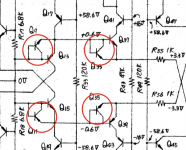
Any idea what the marked parts do? Some limiter?
Attachments
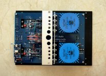
More or less finished the test platform.
An outdated version of the F5-HA board was sacrificed as a "Mother Board" for power supply wiring.
Will probably be ready for independent audition end of next week.
Patrick
.
An outdated version of the F5-HA board was sacrificed as a "Mother Board" for power supply wiring.
Will probably be ready for independent audition end of next week.
Patrick
.
Attachments
Reverse protection ?
Patrick
Yes, of course! Why didn't I see that?
I have been listening to the diamond buffer version of the amp in the past 2 days, and it sounds very nice
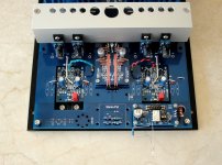
Very nice build cwtim... pleasing to the eye.
All these circuits are so tempting... and I like the very compact size even with TO92 devices.
Need to have a listen myself... which is probably just around the corner.
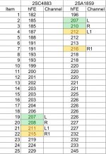
UPS was fast, so I received a package from Digi-Key today. I measured the hFE values of the 2SC4883/2SA1859 devices and the results are on the attached table. According to my understanding I should choose the green or yellow marked pairs so that I would have minimun differences within pairs and L/R channels. What say you?
Attachments
Correct.
If you want to be real precise then you need to measure hfe at operating current, with e.g. a curve tracer.
You can also supply a base current of say 0.7mA and then measure collector current.
Set Vce to 15V, and calculate hfe from current ratio.
Make sure you put the device on a heat sink.
Patrick
If you want to be real precise then you need to measure hfe at operating current, with e.g. a curve tracer.
You can also supply a base current of say 0.7mA and then measure collector current.
Set Vce to 15V, and calculate hfe from current ratio.
Make sure you put the device on a heat sink.
Patrick
Last edited:
I was also surprised by the performance, and that it did not receive more attention all these years.
I suspect this sentiment was not universal in the AES hierarchy.
with none of the detrimental effects of feedback loops.
- Home
- Amplifiers
- Headphone Systems
- The Pioneer Super Linear Circuit