Hi,
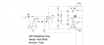
I am planning to layout the simple HPA by ESP. I have modified the sch a bit by including thiele ckt and some other refinements based on some reading here.
I would like to know if I am on the right track and if some thing else is required to be added/optimized. gain could be around 8-12 by adjusting R4.
would it be a good idea to place the inductor on the PCB itself or somewhere else.?
regards
Prasi
pl feel free to remove sch /delete the post if it violates copyright.
Attachments
check my thread with TPA .... it is the best what I built yet, you can try layout own PCB (I can also ship you pair of PCBs without no charge (I am not profiting in this and I never will be) - if you will, they left me for 3 amps) ... you can build it only with one pair laterals - two pair was only my sound test, but I have not noticed difference in sound ...
edit: ok, now I see you have this for headphones and my amp is for speakers ... but anyway ...
edit: ok, now I see you have this for headphones and my amp is for speakers ... but anyway ...
Last edited:
I've built this design on stripboard and it works quite well - however depending on the source and the headphones you are using, you will definitely want to reduce the gain!!
I used this first time with my PC, and with 32 ohm headphones it is capable of blowing your eardrums to pieces with the default gain. I found a gain of two was plenty, and 9V rails were plenty.
I used this first time with my PC, and with 32 ohm headphones it is capable of blowing your eardrums to pieces with the default gain. I found a gain of two was plenty, and 9V rails were plenty.
I've built this design on stripboard and it works quite well - however depending on the source and the headphones you are using, you will definitely want to reduce the gain!!
I used this first time with my PC, and with 32 ohm headphones it is capable of blowing your eardrums to pieces with the default gain. I found a gain of two was plenty, and 9V rails were plenty.
OK thank you Jaycee. I would keep that in mind.
Regards
Prasi
I think this will sound very good and neutral. It will have very low THD but sound uninspiring. There are so many ways to power headphones and headphones is the perfect place for Single Ended Class A with cap coupled output.
On this ESP amp, it's already cap coupled input, why not add a couple of caps for output coupling? Try 1000uF Panasonic FR bypassed with 10uF Silmic II. You will avoid need for DC protect and passively prevent headphones from ever getting destroyed should one side of the push pull circuit go bad.
That 22pF on C5 needs to be determined empirically in small increments, make large enough to prevent oscillation but a few pF too much and sound can become lifeless. Specify NP0/C0G SMT here as close to pins on opamp as possible.
Add three BF862's in a single Ended preamp (Juma's deign) and it will sound more musical.
You could power it from 15v to 18v single rail and it will work fine.
Here was my hand made layout:
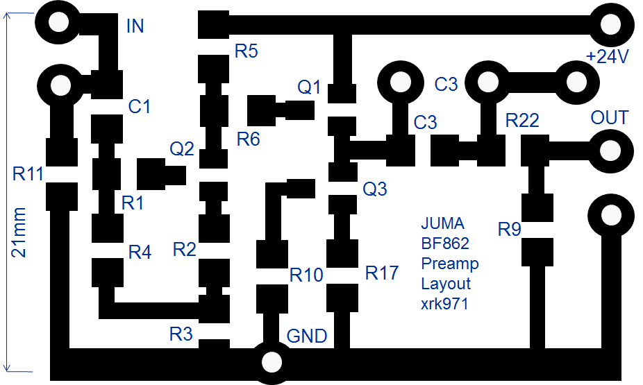
But maybe this is straying too far from the intended purpose of the ESP HPA?
You could power it from 15v to 18v single rail and it will work fine.
Here was my hand made layout:
But maybe this is straying too far from the intended purpose of the ESP HPA?
Last edited:
if you are connecting a pair of low impedance headphones to the output of the JFET circuit above you will have bass roll off starting at about 500 Hz - the 10uF coupling cap needs to be about 470uF. However, for decent sound, I think the earlier design would be better - greater drive.
For a headphone amplifier, assuming c. 2V input from a CD player, you will need a gain of 5x. If the output is from a phono stage, typically 300mV or so, a gain of 10-15 will suffice.
Here is another option for you - class A headphone amp: http://hifisonix.com/wordpress/wp-content/uploads/2011/02/A-Universal-Small-Signal-Class-A-Buffer-V1.0.pdf
if you are connecting a pair of low impedance headphones to the output of the JFET circuit above you will have bass roll off starting at about 500 Hz - the 10uF coupling cap needs to be about 470uF. However, for decent sound, I think the earlier design would be better - greater drive.
For a headphone amplifier, assuming c. 2V input from a CD player, you will need a gain of 5x. If the output is from a phono stage, typically 300mV or so, a gain of 10-15 will suffice.
Here is another option for you - class A headphone amp: http://hifisonix.com/wordpress/wp-content/uploads/2011/02/A-Universal-Small-Signal-Class-A-Buffer-V1.0.pdf
Prasi,it seems that you have to draw another pcb!
")
if you are connecting a pair of low impedance headphones to the output of the JFET circuit above you will have bass roll off starting at about 500 Hz - the 10uF coupling cap needs to be about 470uF. However, for decent sound, I think the earlier design would be better - greater drive.
For a headphone amplifier, assuming c. 2V input from a CD player, you will need a gain of 5x. If the output is from a phono stage, typically 300mV or so, a gain of 10-15 will suffice.
Here is another option for you - class A headphone amp: http://hifisonix.com/wordpress/wp-content/uploads/2011/02/A-Universal-Small-Signal-Class-A-Buffer-V1.0.pdf
This was just going to be a preamp to feed the ESP in order to imbue it with SE Class A liveliness. As a direct headamp, I replaced the output JFET with a MOSFET to get my pocket Class A headphone amp.
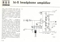
Delange, the elektor circuit look very similar to the ESP.
Yes it does. I posted my experiences because of that.
The value of the feedback resistor is a bit high to my taste on the Elektor circuit but you could easily recalculate the gain (R3 and R4) and use a lower value. The LF356 opamp has slightly better noise specs than the TL072. And the Elektor version uses a higher bias.
It shows you could have fun trying to tweak the designs
This was just going to be a preamp to feed the ESP in order to imbue it with SE Class A liveliness. As a direct headamp, I replaced the output JFET with a MOSFET to get my pocket Class A headphone amp.
What value coupling cap did you use?
Hi Prasi, I designed this amp some time ago, but with OPA134 (single opamp).I tested it with different headphones - IMHO: it sound better with Gain x 23 and 120 Ohm output resistor (better bass).
Attachments
What value coupling cap did you use?
On the mosfet headphone amp, I started with 390uF, which works well for 250ohm headphones, but lately have gone as high as 2000uF for low impedance but high sensitivity IEMs. The amp seems to work well with a wide range of headphones as feedback on thread has been very positive. Surprisingly, many people have said it drives LCD-2's better than their desktop amps.
More here:
xrk971 Pocket Class A Headamp GB
There's about 150 PCBs out all over the world at this point and most everyone loves the sound. It's a simple amp so and easy first project for diy, even though SMT based.
Prasi,it seems that you have to draw another pcb!
Sure thimios, I will do it.
but let this be project for near future for me.
I am getting involved in ESP HPA ( as its making me learn a lot of things), and I am trying to make it stable against any load/ headphones, with thiele ckt and a cap from 'out' to 'in-'. Plus an input filter so that DAC noises do not get through to o/p stages. + like Xrk suggested, o/p cap so as not to worry about headphone DC protection.
The ckt suggested/designed by bonsai will be put to service here on DIYA if I may have the permission from him.
regards
Prasi
edit: somewhat complicated english in above post, I hope the meaning is conveyed.
Hi Prasi, I designed this amp some time ago, but with OPA134 (single opamp).I tested it with different headphones - IMHO: it sound better with Gain x 23 and 120 Ohm output resistor (better bass).
I do not know how I missed your post, but thanks a lot for posting your experience.
Now, could you or some one answer this question.
Would the inline resistor be better off after the thiele circuit (consisting of zobel and inductor // 10 ohm resistor) or before it?
On the mosfet headphone amp, I started with 390uF, which works well for 250ohm headphones, but lately have gone as high as 2000uF for low impedance but high sensitivity IEMs. The amp seems to work well with a wide range of headphones as feedback on thread has been very positive. Surprisingly, many people have said it drives LCD-2's better than their desktop amps.
More here:
xrk971 Pocket Class A Headamp GB
There's about 150 PCBs out all over the world at this point and most everyone loves the sound. It's a simple amp so and easy first project for diy, even though SMT based.
Very nice!
Sure thimios, I will do it.
but let this be project for near future for me.
I am getting involved in ESP HPA ( as its making me learn a lot of things), and I am trying to make it stable against any load/ headphones, with thiele ckt and a cap from 'out' to 'in-'. Plus an input filter so that DAC noises do not get through to o/p stages. + like Xrk suggested, o/p cap so as not to worry about headphone DC protection.
The ckt suggested/designed by bonsai will be put to service here on DIYA if I may have the permission from him.
regards
Prasi
edit: somewhat complicated english in above post, I hope the meaning is conveyed.
No problem Prasi - please go ahead.
- Status
- This old topic is closed. If you want to reopen this topic, contact a moderator using the "Report Post" button.
- Home
- Amplifiers
- Headphone Systems
- ESP HPA