No problem Prasi - please go ahead.
thank you very much Bonsai!
Hi Prasi,
I built up one channel of the ESP HPA on veroboard with an LME49740 (will use two chan of a quad). It oscillated badly at first. I had to add a 680pF input low pass film cap filter to block RF in, I added output Thiele 100nF film and 4.7R (which also blocks RF feeding in from headphone cable), and added 33pF silver mica across 22k feedback resistor. Probably had a lot to do with P2P layout as Elliot warned about if doing in veroboard. It's stable now and plays music. I am not sure what the bias is supposed to be but quiescent is very low at 2mA. When it was oscillating (400kHz and 8v p-p), and bias measured 150mA.
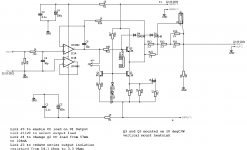
I built it according to this circuit (I using nice Silmic II 100uF for C2, and 1uF 63v Wima MKS on C1):

Now stable, no input, output measures 0.0mVac on Fluke 101 and 115. But if I turn volume up on my preamp (Focusrite 2i2 DAC), the Fluke 115 (true rms) will show increasing noise - hiss amplified from DAC. But even at 0.0mV it is not dead quiet on headphones. On scope, I can still see about 4mV of high frequency hash. Not really audible when music playing, but not dead quiet like my SE Class A discrete headphone amps that I am used to building. I wonder if this is opamp noise? This LME49740 had very good noise specs though.
Anyhow, listening to it in pseudo stereo and sounds decent. Just puzzled by the low quiescent bias current - is that normal? If I want to turn this to Class A with 120mA bias current all the time, is it as simple as changing 10R emitter resistors to smaller value (maybe 2.2R?).
Actually I want to use this not as a headphone amp but a powerful instrumentation amp where I need to have low distortion signal to drive a sensor. Having a simple push-pull pair of BD139/140's seemed to be a good way to give an opamp some muscle.
You will recognize that I am using the shunt regulator (nice PSU) from your Juma BJT HPA project.")
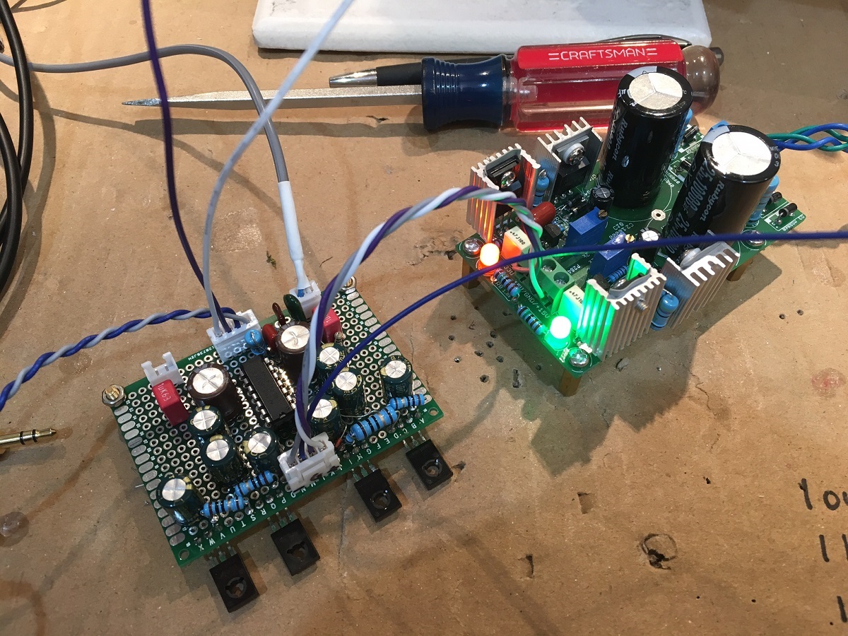
Here is a photo showing amp with just left channel wired up (components are in place on right but no wires connected yet).
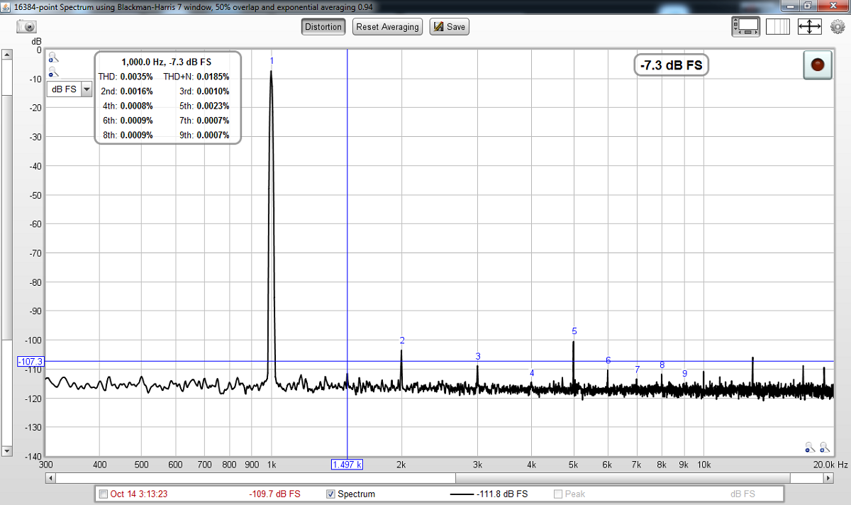
Here is quick FFT driving 700mV into the on-board 4.7R/100nF (Thiele) load. Not bad, but has some elevated 5th harmonic. Dominant 2nd is nice to have rather than 3rd.
I think bass authority could be improved if we change those emitter resistors to smaller value. But in general, probablyI agree with your choice to add input filtering,and output Thiele. It would be good idea to include a feedback compensation capacitor pad in parallel across R4 for a 5mm pitch silver mica (circa 33pF) But looks like a worthwhile PCB layout and certainly I would use it if you finished the layout. Thanks for doing this - the circuit actually sounds surprisingly good for how simple it is.
I should mention that one benefit of using an opamp on the input gain stage (with some negative feedback) is that the DC offset is automatically servo controlled to zero. This is DC coupled output and I measure 0.0mV DC offset and it is always so.
Thanks,
X
I built up one channel of the ESP HPA on veroboard with an LME49740 (will use two chan of a quad). It oscillated badly at first. I had to add a 680pF input low pass film cap filter to block RF in, I added output Thiele 100nF film and 4.7R (which also blocks RF feeding in from headphone cable), and added 33pF silver mica across 22k feedback resistor. Probably had a lot to do with P2P layout as Elliot warned about if doing in veroboard. It's stable now and plays music. I am not sure what the bias is supposed to be but quiescent is very low at 2mA. When it was oscillating (400kHz and 8v p-p), and bias measured 150mA.
I built it according to this circuit (I using nice Silmic II 100uF for C2, and 1uF 63v Wima MKS on C1):
Now stable, no input, output measures 0.0mVac on Fluke 101 and 115. But if I turn volume up on my preamp (Focusrite 2i2 DAC), the Fluke 115 (true rms) will show increasing noise - hiss amplified from DAC. But even at 0.0mV it is not dead quiet on headphones. On scope, I can still see about 4mV of high frequency hash. Not really audible when music playing, but not dead quiet like my SE Class A discrete headphone amps that I am used to building. I wonder if this is opamp noise? This LME49740 had very good noise specs though.
Anyhow, listening to it in pseudo stereo and sounds decent. Just puzzled by the low quiescent bias current - is that normal? If I want to turn this to Class A with 120mA bias current all the time, is it as simple as changing 10R emitter resistors to smaller value (maybe 2.2R?).
Actually I want to use this not as a headphone amp but a powerful instrumentation amp where I need to have low distortion signal to drive a sensor. Having a simple push-pull pair of BD139/140's seemed to be a good way to give an opamp some muscle.
You will recognize that I am using the shunt regulator (nice PSU) from your Juma BJT HPA project.
Here is a photo showing amp with just left channel wired up (components are in place on right but no wires connected yet).
Here is quick FFT driving 700mV into the on-board 4.7R/100nF (Thiele) load. Not bad, but has some elevated 5th harmonic. Dominant 2nd is nice to have rather than 3rd.
I think bass authority could be improved if we change those emitter resistors to smaller value. But in general, probablyI agree with your choice to add input filtering,and output Thiele. It would be good idea to include a feedback compensation capacitor pad in parallel across R4 for a 5mm pitch silver mica (circa 33pF) But looks like a worthwhile PCB layout and certainly I would use it if you finished the layout. Thanks for doing this - the circuit actually sounds surprisingly good for how simple it is.
I should mention that one benefit of using an opamp on the input gain stage (with some negative feedback) is that the DC offset is automatically servo controlled to zero. This is DC coupled output and I measure 0.0mV DC offset and it is always so.
Thanks,
X
Attachments

Last edited:
Hi X,
Nicely built and thanks for sharing.
Yes, ESP warns about capacitive coupling and oscillation possibility due to wide bandwidth.
I wonder why the 5th harmonic is so dominant as it is a very conventional design.
Yes I recognize the Nazar shunt regulator (It gave me plenty of problems due to wrong resistor and fake IC).
Do share your stereo experience.
Yes, Syr posted here that 120ohm inline resistor helped with bass authority. You could try the same.
regards
Prasi
Last edited:
Hi X,
Nicely built and thanks for sharing.
Yes, ESP warns about capacitive coupling and oscillation possibility due to wide bandwidth.
I wonder why the 5th harmonic is so dominant as it is a very conventional design.
Yes I recognize the Nazar shunt regulator (It gave me plenty of problems due to wrong resistor and fake IC).
Do share your stereo experience.
Yes, Syr posted here that 120ohm inline resistor helped with bass authority. You could try the same.
regards
Prasi
I forgot what the woes were with the Nazar - it works fine now, but I do recall it took a change somewhere to get the full adjutment capability. It is very stable now though. Funny thing is I am using some nice audio grade Toshiba BJT's for the shunts - just because that was all I had on had at the time.
"Audiphool grade shunt reg"
I should mention that I put the ESP HPA on a scope and cranked the output up to see what max drive into high impedance load was and it was impressive at 28v p-p before clipping. That will do nicely for my need for 24v p-p as instrument power amp with room left over.
"Audiphool grade shunt reg"
I should mention that I put the ESP HPA on a scope and cranked the output up to see what max drive into high impedance load was and it was impressive at 28v p-p before clipping. That will do nicely for my need for 24v p-p as instrument power amp with room left over.
Thats really nice. i wonder if it can be used as a small power amp for sensitive speakers as suggested by esp.
Prasi,it seems that you have to draw another pcb!
Thimios,
as promised.
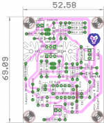
Just a rough layout to see if single sided is possible..I know you only need diy friendly PCB's.
So here it is, I will refine it a bit further and post pdfs.
It unfortunate that we dont have Bonsai here on diya anymore to guide us.
regards
Prasi
Attachments

Last edited:
That Class A buffer from Bonsai (too bad he is no longer on DIYA) looks really nice too. Very useful moderate power instrumentation amp.
I should point out that using an Apex FX8, sans lateral MOSFET output stage and replacing all transistors with higher voltage variants like 2N5551/5401 and KSC3503/KSA1381, one can also make a nice Class A buffer with higher voltage output (I have run at +/-50V) and it is quite low in distortion too. It can swing 80v p-p no problem.
I should point out that using an Apex FX8, sans lateral MOSFET output stage and replacing all transistors with higher voltage variants like 2N5551/5401 and KSC3503/KSA1381, one can also make a nice Class A buffer with higher voltage output (I have run at +/-50V) and it is quite low in distortion too. It can swing 80v p-p no problem.
Last edited:
I've built this design on stripboard and it works quite well - however depending on the source and the headphones you are using, you will definitely want to reduce the gain!!
I agree.
Change gain about 5x is good compromise for many headphone impedance, I think.
Hi Prasi,
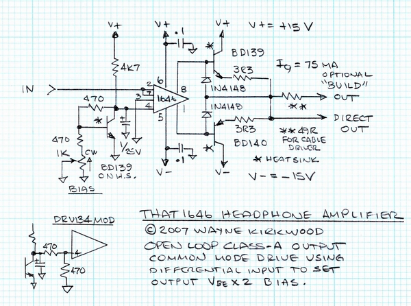
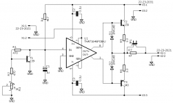
I have another one for you that is similar to the title circuit but is Class A and uses a very low distortion THAT differential input driver. It's a clever way to control the bias too. I think Kirkwood is a designer from THAT Corp? If you have time, pllease consider making another layout.
Thanks,
X
I have another one for you that is similar to the title circuit but is Class A and uses a very low distortion THAT differential input driver. It's a clever way to control the bias too. I think Kirkwood is a designer from THAT Corp? If you have time, pllease consider making another layout.
Thanks,
X
Attachments
Thimios,
as promised.
Just a rough layout to see if single sided is possible..I know you only need diy friendly PCB's.
So here it is, I will refine it a bit further and post pdfs.
It unfortunate that we dont have Bonsai here on diya anymore to guide us.
regards
Prasi
Thanks prasi!That Class A buffer from Bonsai (too bad he is no longer on DIYA) looks really nice too. Very useful moderate power instrumentation amp.
I should point out that using an Apex FX8, sans lateral MOSFET output stage and replacing all transistors with higher voltage variants like 2N5551/5401 and KSC3503/KSA1381, one can also make a nice Class A buffer with higher voltage output (I have run at +/-50V) and it is quite low in distortion too. It can swing 80v p-p no problem.
What you mean saying that Bonsai isn't in DIYA anymore?
Thanks prasi!
What you mean saying that Bonsai isn't in DIYA anymore?
Yes thimios, I too came to know after looking at his profile.
here are the files. also attached is his website document (linked by him) for convenience.
regards
Prasi
Attachments
Last edited:
Hi Prasi,
I have another one for you that is similar to the title circuit but is Class A and uses a very low distortion THAT differential input driver. It's a clever way to control the bias too. I think Kirkwood is a designer from THAT Corp? If you have time, pllease consider making another layout.
Thanks,
X

can you pl confirm sch? I might have misread it and I have a very different symbol or 1646.
Attachments
Hi Prasi,
I am not 100% sure but the notes say that the differential input is used to set bias, and the common mode feedback is used for the signal, and the amp runs open-loop (zero global feedback) so it is a different implementation than the usual opamp driving a push-pull stage. This is actually very clever and might make a nice ZGF Class A amp.
Here is the data sheet for anyone interested. Perhaps the way to really check if this the case is for me to vero board it. My 1646 is an SOIC8, but luckily I have a DIP8 adapter board.
http://www.thatcorp.com/datashts/THAT_1606-1646_Datasheet.pdf
For now, I would redraw the schematic per the drawing pin outs.
Thanks,
X
Hi Prasi,
I am not 100% sure but the notes say that the differential input is used to set bias, and the common mode feedback is used for the signal, and the amp runs open-loop (zero global feedback) so it is a different implementation than the usual opamp driving a push-pull stage. This is actually very clever and might make a nice ZGF Class A amp.
Here is the data sheet for anyone interested. Perhaps the way to really check if this the case is for me to vero board it. My 1646 is an SOIC8, but luckily I have a DIP8 adapter board.
http://www.thatcorp.com/datashts/THAT_1606-1646_Datasheet.pdf
For now, I would redraw the schematic per the drawing pin outs.
Thanks,
X
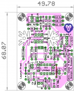
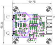
here is a quick 50x50 layout
Attachments

I can't understad what happen.....
Pete,Esperado and now Bonsai
I think because critics from some people to showing their superiority.
They do not want help DIY community to make better design or share their design.
....I think Kirkwood is a designer from THAT Corp?...
I believe Wayne has worked with, not for, THAT Corp.
However both the THAT Corp designers and Wayne are very sharp people.
here is a quick 50x50 layout
Thank you, Prasi. Looks very nice and love the tiny 50mm format. One thing though, I think T1 is a big BD139 because it needs to match the output as close as possible to be a Vbe multiplier for temperature compensation. Thus, I think T1 need to be on the same heatsink as the two outputs, preferably in between the two. That may require some work though and if you are not up to it, I can use flying leads on T1 to relocate it to the main heatsink.
Thank you, Prasi. Looks very nice and love the tiny 50mm format. One thing though, I think T1 is a big BD139 because it needs to match the output as close as possible to be a Vbe multiplier for temperature compensation. Thus, I think T1 need to be on the same heatsink as the two outputs, preferably in between the two. That may require some work though and if you are not up to it, I can use flying leads on T1 to relocate it to the main heatsink.
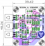
mounting all BD's inline would result in something like this
.Attachments

- Status
- This old topic is closed. If you want to reopen this topic, contact a moderator using the "Report Post" button.
- Home
- Amplifiers
- Headphone Systems
- ESP HPA