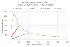
Note the distortion depends on output power and load resistance. So micromanaging the circuit for lowest value with 32 ohms won't guarantee optimal performance into 120 ohms, or vice versa.
60 ohms is a nice target value, as it is the geometric mean between 30 and 120 ohms, a range that covers a wide range of models.
60 ohms is a nice target value, as it is the geometric mean between 30 and 120 ohms, a range that covers a wide range of models.
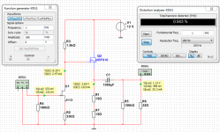
IRF610 will be alright.
Most people have 610.
It is possible I could fix lower distortion with 12 Volt.
But the difference will not be very big.
I will see what I can do with J113 and IRF610.
How about Fairchild FQP3N30/FQP3P20? It was my impression these newer mosfets were a little better than IRF.
Yes, of course it depends and there are headphones on very different impedance.Note the distortion depends on output power and load resistance. So micromanaging the circuit for lowest value with 32 ohms won't guarantee optimal performance into 120 ohms, or vice versa.
60 ohms is a nice target value, as it is the geometric mean between 30 and 120 ohms, a range that covers a wide range of models.
But I have a feeling many have 32 Ohm headphone.
I have.
60 Ohms load will get better figures than 32 Ohms in spice.
That I am almost sure of.
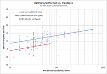
See my survey about headphones impedance.
There is an optimal impedance defined by the bias current and voltage.
I haven't done the calculation for the J-Mo, but the Sapphire amp is configured around this idea.
I haven't done the calculation for the J-Mo, but the Sapphire amp is configured around this idea.
Attachments
Last edited:
ended up with a IR511 for the NMOS, used the biasing resistors from the OP and 9V supply. Worked first try! About 2x voltage gain open circuit, drops very slightly driving 32 ohm phones, rock solid for 130 ohm ")
I was reading through the thread though and wondering, should i change the 1k for the JFET to 2.2k for 130ohm use? Already found a matching pair of the JFETs(actiually a closely matching quad ) so i am concidering building a "proper" and stereo one on some perf and putting it in a case
I was reading through the thread though and wondering, should i change the 1k for the JFET to 2.2k for 130ohm use? Already found a matching pair of the JFETs(actiually a closely matching quad
) so i am concidering building a "proper" and stereo one on some perf and putting it in a caseMaybe not much of a looker but it works great
PSU could do with a choke probably as there is a very tiny amount of humm you can hear if you are in a quiet room with no signal input.
Ended up going for the medium impedance version with one change being the 33ohm resistor swapped for a 30ohm because I had a dual 5W precision part laying around.
Ended up using the BF245A and IRF511 and they seem just fine.
PSU is very simple, 15V wall adapter and a L7812CV with 1uF ceramics on the input and output.
Sound is great, very clear stereo separation. I find that it much more clearly depicts if an instrument is center-left or center-right rather than purely center mixed when listening with my case swapped HP-50As. Very interesting indeed!
Maybe not much of a looker but it works great
Wait, you aren't going to show us the insides? What heresy is this?!
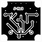
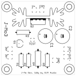
I'm gona design my own boards to suit the components I have on hand and to help some friends learn some board design.
A few component amp like this is imo a pretty good start to learning board design. Not much to keep track off and you get something cool when you're done
A few component amp like this is imo a pretty good start to learning board design. Not much to keep track off and you get something cool when you're done
@bananasplit_00
These may be useful to you.
These may be useful to you.
Attachments
@bananasplit_00: What's so special to ROE capacitors? I have several values, NOS, they are ok, but not so exact measuring, some of them display even 40-50% bigger capacity. I know in the 70's or 80's they had a good name, but why should someone use them, especially in the audio path? If there's something great with them, please let me know...at least mine don't measure so good regarding ESR...
- Home
- Amplifiers
- Headphone Systems
- JFET-MOSFET headphone amplifier J-Mo 3