Hey guys. I've recently acquired a used Lehmann Black Cube Linear headamp to use with my Sennheiser HD800 & Matrix X-Sabre DAC.
After a couple weeks listen which I enjoyed but found it short on clarity & a little distant, I opened her up. Along with the schematic, I removed 2 input capacitors on each channel (a 22nF & 1.5uF in parallel).
I then ran elcheapo 20AWG wires from the input RCA direct to the Alps RK 27 PCB pins. The leads run under the PCB the length of the chassis.
Here's the question: The sound is now clearer as expected, but the soundstage has widened too much and I've lost stage depth. The bass richness & impact seems to have lessened too.
I'm puzzled [emoji53]. Some music is less enjoyable, some more.
Can you explain why?
Sent from my LG-D855 using Tapatalk
Last edited:
You are hearing the way the source actually is presenting it, or more so than with the capacitors
The capacitors have some distortion and non-linearness which place emphasis on certain frequencies which you perceive as bass or depth based on what you are listening to. Also, there is a frequency cut off presented with the capacitors in place.
But if your dac is outputting D.C. (The capacitors are there to block D.C. from the source) you may be hearing something else which may be not good. D.C. on the output the tour headphones or the input ic struggling with the D.C.
Also, your wire choice may influence the sound. Perhaps more than the caps.
Some people like warm and romantic. The sound of a cap may be preferred but it is farther from what the source is playing.
You are hearing the way the source actually is presenting it, or more so than with the capacitors
Yes, and the volume control may also affect the sound as much.
Food for thought so far. Thanks. I'm going to take some measurements & do some more listening.
A thought: In original setup, the RCA inputs fed a common ground at the end of the PCB which then ran a single trace to the front POT. Many ground VIAs along the way. In my setup, I ran 2 separate ground wires direct to separate POT pins, bypassing the trace. Ground loop?
A thought: In original setup, the RCA inputs fed a common ground at the end of the PCB which then ran a single trace to the front POT. Many ground VIAs along the way. In my setup, I ran 2 separate ground wires direct to separate POT pins, bypassing the trace. Ground loop?
Usually designers don't put DC input decoupling for nothing, so removing them is not a good idea.
If you remove them, you DC couple the output of the previous stage, with the input of your amplifier, whose inner input might not like at all to be at ground level.
As a trivial example, take this utter simple, one BJT amplifier:
If you bypass C1, you wire the base of the BJT to 0V, and it will be distorting as hell.
Or, if for any reason there is some DC component in input, the bias of the BJT will be totally off.
Some other amplifiers might even go in smoke.
If you remove them, you DC couple the output of the previous stage, with the input of your amplifier, whose inner input might not like at all to be at ground level.
As a trivial example, take this utter simple, one BJT amplifier:
An externally hosted image should be here but it was not working when we last tested it.
If you bypass C1, you wire the base of the BJT to 0V, and it will be distorting as hell.
Or, if for any reason there is some DC component in input, the bias of the BJT will be totally off.
Some other amplifiers might even go in smoke.
No, much less than the caps. Unless the problem is that an unshielded wire was used from the RCA so it picks up hum and interference.Hikari1 said:Also, your wire choice may influence the sound. Perhaps more than the caps.
The input caps block DC, so keep your amp safe. They add a high pass filter, to block very low frequencies. The fact that the main input cap is bypassed may add a high frequency notch.
Changing the grounding may have made a difference, possibly a bigger difference than omitting the caps. It all depends on the details of the circuit.
Why change the circuit? Did you believe that the original designer got it wrong?
The purpose of the mod, as with any I do, is to attempt to improve the sound quality. This amp has great tonality but was missing clarity - a bit veiled. Upon research of the schematic, seeing caps in the signal path, which are often audible, was the reason for doing so. The DAC feeding it was the flagship model from Matrix so I didn't figure it would need DC blocking.
Before I did the mod, I took some measurements with RMAA. I've been using this for years whenever I want to examine a new piece of audio electronics. The ADC is a E-MU 0204 hooked up to a 2nd PC. The source is my desktop playing from Foobar in WASAPI mode with Windows Mixer Enhancements disabled. After initial testing of the amp alone, final tests are done with the headphones connected in parallel, with the ear pads mounted flush on a headphone stand to replicate the electrical & acoustic impedance of the phones being on my head. Why? To simulate real world usage.
As suggestions are indicating that the mod may be a bad thing, just now, I completed the same test routine with the modified Lehmann amp to examine what may be happening.
Both good and bad news.
Good new, no negative changes & slight improvement. Noise lowered 0.9dB; 1kHz THD identical; IMD figures identical but there is one strange anomaly at 300Hz in the graph with the mod; THD Swept Tones showed approx 1dB full better with the mod.
Bad news: Nothing unusual shown which doesn't help.
So, armed with this measurement and the following schematic of a replica, do you still think my mod has caused a problem?
PS - I know the free version of RMAA limits what you can see and the software doesn't get much development but I'm very familiar with it and have made myself a library of test results. If you know of a better app, I'm all ears.
Before I did the mod, I took some measurements with RMAA. I've been using this for years whenever I want to examine a new piece of audio electronics. The ADC is a E-MU 0204 hooked up to a 2nd PC. The source is my desktop playing from Foobar in WASAPI mode with Windows Mixer Enhancements disabled. After initial testing of the amp alone, final tests are done with the headphones connected in parallel, with the ear pads mounted flush on a headphone stand to replicate the electrical & acoustic impedance of the phones being on my head. Why? To simulate real world usage.
As suggestions are indicating that the mod may be a bad thing, just now, I completed the same test routine with the modified Lehmann amp to examine what may be happening.
Both good and bad news.
Good new, no negative changes & slight improvement. Noise lowered 0.9dB; 1kHz THD identical; IMD figures identical but there is one strange anomaly at 300Hz in the graph with the mod; THD Swept Tones showed approx 1dB full better with the mod.
Bad news: Nothing unusual shown which doesn't help.
So, armed with this measurement and the following schematic of a replica, do you still think my mod has caused a problem?
An externally hosted image should be here but it was not working when we last tested it.
PS - I know the free version of RMAA limits what you can see and the software doesn't get much development but I'm very familiar with it and have made myself a library of test results. If you know of a better app, I'm all ears.
MKT is polyester dielectric, so very slightly nonlinear. Perhaps not the best choice. However, signal levels will be fairly low and the LF rolloff is at 2Hz so there will not be much signal across the cap from 20Hz up. I assume this cap is fairly large so that might explain the noise when in circuit, due to stray capacitance.
The rest of the circuit is just a fairly standard augmented opamp. I note that there is no output coupling capacitor so that endangers the headphones in the event of a circuit fault. It also means that the input coupling cap is the only LF rolloff.
If it was my amp and I wanted to mod it I think I might try replacing the input caps with something like a 0.22uF or 0.47uF polypropylene, and think about adding an output cap.
That schematic has neither global feedback, nor a DC servo, and it can have some gain, so, without input decoupling capacitors, any DC component in input will be amplified (if the 680 Ohm resistor is wired, up to ~8 times) and set to the headphones.
I personally do not believe that any decent capacitor (that schematic, as component choice, reveals someone who has thought about quality - assuming parts are OEM and not clones) when made work within its limits (and especially in the input, with low/to-zero DC component across it), is going to affect sound quality.
This is a good read, in case you have no already:
Capacitor Characteristics
And this:
Blog - How Much Distortion Can We Hear With Music? | Axiom Audio
It may reveal someone who believes that 'quality' is found in particular component brands. It may reveal someone who believes that such brands are more important than getting the circuit right. Or maybe it just reveals what he assumes about the knowledge of his customers and reviewers. Sending DC to headphones is unlikely to improve the sound.HotIce said:that schematic, as component choice, reveals someone who has thought about quality - assuming parts are OEM and not clones
https://www.lehmannaudio.com/headphone-amplifiers/home/linear.html
That's a lot of super glowing reviews for what appears to be simply an opamp with a BC550/560 and BD139/140 output stage?
Where is the innovation in this?
That's a lot of super glowing reviews for what appears to be simply an opamp with a BC550/560 and BD139/140 output stage?
Where is the innovation in this?
The purpose of the mod, as with any I do, is to attempt to improve the sound quality. This amp has great tonality but was missing clarity - a bit veiled.
As the schematic is a Lehmann (as xrk is pointing out) its very close indeed to one I had a play with a while back, wrote it up on my blog - http://www.diyaudio.com/forums/blogs/abraxalito/1250-bargain-beaut-headphone-amp.html
The TL,DR version is the poor dynamics turned out to be a function of the opamp's loading, poor OPS PSRR and also poor grounding. No changes to caps in the signal path were needed for satisfying sound.
So, armed with this measurement and the following schematic of a replica, do you still think my mod has caused a problem?
To get a handle on the noise currents flowing in your grounds, the layout is orders of magnitude more useful than the schematic.
Sorry for the long delay to provide feedback. A computer failure, and 3 weeks illness to blame.
Based on comments & some analysis, I rerouted the 4 signal wires carefully; desoldered the original wires from the board (previously I only desoldered them from the RCA sockets); and desoldered the pre out wires in case of interference from torroidal transformer or external noise.
Glad to report that bass is juicy again, and soundstage has improved. But I'm still finding depth of stage not as great.
So my question is: do you think that the designers choice of joining the signal grounds together at the end of the board (closest to the RCAs) was causing more crosstalk, and thus deepening the stage?
I recall that prior to the mod, the stage was deeper, but the sound was more distant, less clear, less present.
Sent from my LG-D855 using Tapatalk
An externally hosted image should be here but it was not working when we last tested it.
Ye basic noninverting op amp plus open loop diamond buffer affair.
C103,C104 are completely optional. C101,C102 are for safety's sake but if you know the input has no DC offset you can short them out it won't affect the electrical performance of the circuit.
Looking at the rest of the circuit though, I'd have to say that those capacitors are the least of the problems. Ugh. Even the position of the caps is wrong, they should be in series with R13,14 with a 47k resistor added in parallel with C105,106. As it stands the output DC offset will vary with the position of the volume control... a problem they try to alleviate by making R13,14 so large, which adds to the circuit noise. The op amp input impedances are not balanced properly either at DC or audio bandwidth.
Dual op amp - yuck. Dual op amp powered off RC filtered rails - double yuck.
And that diamond buffer. R26,27 and R30,31 are added to goose the output bias current, but they kill the PSRR of the buffer. Also 1.5k for R25,28,29,32 would be better off replaced with current sources for lower distortion, or at the very least increased.
I would put those caps back in, and remove C105 and C106 or reduce their values to maybe 47pF. They shunt highs to ground at the input of the op amp. C103 and C104 are "sweetening" caps, attempting to pass more extreme highs. I would reduce R19 and R20 to 10 Ohms to firm up the supply. Yes, you could be getting DC from your source, and you could be getting extreme lows that are interfering with what you can actually hear.
I just measured DC at source and output of the amp:
DAC: <0.2mV each channel
Amp: 13mV and 9mV
Also, as I have selected unity gain on the switches, volume on the pot is typically 12:00 to Max pending music source. So, what would the effect of removing R13/14 and reducing C105/106 values?
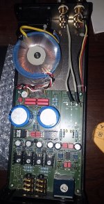
For reference, I've attached a pic of the internals with the current mod. The grey wires are the desoldered Pre Outs. The 4 wires are source and are positioned adjacent to the original PCB traces & soldered direct to the Pot
DAC: <0.2mV each channel
Amp: 13mV and 9mV
Also, as I have selected unity gain on the switches, volume on the pot is typically 12:00 to Max pending music source. So, what would the effect of removing R13/14 and reducing C105/106 values?
For reference, I've attached a pic of the internals with the current mod. The grey wires are the desoldered Pre Outs. The 4 wires are source and are positioned adjacent to the original PCB traces & soldered direct to the Pot
Attachments
Last edited:
The Low Pass filter formed by the R13 & C103 (10K and 100pF) is significant. You can calculate the frequency. R13 is there probably to minimize the change as the pot is moved through its range.
The input circuit does leave much to be desired. The chip datasheet says, "To maintain low distortion, match unbalanced source impedance with the appropriate values in the feedback network as shown in Figure 28." Other's comments were right, using a variable resistor in the input leads to more distortion.
Instead of just removing stuff (it was in there for some reason) I would tweak the values. This is design work.
- Status
- This old topic is closed. If you want to reopen this topic, contact a moderator using the "Report Post" button.
- Home
- Amplifiers
- Headphone Systems
- Please technically explain this audible mod