Without global NFB, the thermal inaccuracies or runaway of the output stage is uncompensated, and very risky for the earphones live.
The degeneration from the big 10 ohm emitter resistors takes care of that.
Here's an interesting question:
If I were to bypass the whole opamp stage, ie. run a short from the 10k R13 /C105 low pass filter direct to the other side of R23/R24 to so that only the diamond buffer is active (or if necessary, desolder the necessary bits), would the input impedance be sufficient (10K + BC550 / BC560) considering I'll use most of the attenuator range.
Any problem with this? I don't need gain.
The degeneration from the big 10 ohm emitter resistors takes care of that.
I don't agree. If outputs goes, for example, 10V positive or negative, there is nothing that can counteract this deviation, but can damage earphone´s moving coils.
No. The op amp is the driver in this circuit. All this guessing around is futile. What is your goal?
You bought a not-very-good-sounding headphone amp, and you want to gut it out because you don't want to learn anything about design work. It certainly is not done by hacking and cutting.
Read what designers are writing about headphone amp circuits, or buy one that sounds good already.
You bought a not-very-good-sounding headphone amp, and you want to gut it out because you don't want to learn anything about design work. It certainly is not done by hacking and cutting.
Read what designers are writing about headphone amp circuits, or buy one that sounds good already.
It certainly is not done by hacking and cutting.
Unless he is a rich man and can buy dozens of earphones, and when one of them gets burned, simply discard the item and start from zero with another new. Not very "engineering techniques".
If you are rich, get a new one. If you are not, then learn something about the technology and improve it. Learning is free, and with the Internet, there is no reasonable limit to learning. But just to cut stuff out of the circuit, rather than studying the problem, is foolish. Has he even read the datasheet of ANY op amp before? It is one of the most foundational parts there is, and this is a fairly standard FET-input op amp. You don't need a college degree, just the interest to learn. It is not a great circuit, but it can be made much better through understanding WHY it is a bad circuit, and WHY it does not sound good.
Is this DIYAudio? A place where hobbyists & curious go to ask questions, discuss ideas, discuss audio circuits? Mostly for the intent on IMPROVING sound?If you are rich, get a new one. If you are not, then learn something about the technology and improve it. Learning is free, and with the Internet, there is no reasonable limit to learning. But just to cut stuff out of the circuit, rather than studying the problem, is foolish. Has he even read the datasheet of ANY op amp before? It is one of the most foundational parts there is, and this is a fairly standard FET-input op amp. You don't need a college degree, just the interest to learn. It is not a great circuit, but it can be made much better through understanding WHY it is a bad circuit, and WHY it does not sound good.
If I were to "buy one that sounds good already" how does that help me learn? How does that help me figure how to make this one better?
Am I asking questions to learn & understand?
Define learning! Is it reading hundreds of pages on a thread to try make sense of one particular circuit?
Nobody put a gun to your head and told you to respond to my thread. There's no need to be condescending.
I have read several op amp data sheets including this one's. They don't answer my questions:
1. Does connecting input grounds immediately affect soundstage depth through cross talk?
2. Can the buffer stand alone in the circuit?
3. Why does it sound the way it does?
Sent from my LG-D855 using Tapatalk
You have not shown your measurement results. When trying to optimize a design it is important to know what the starting point is. E.g. the noise, is it white noise or is is power supply related hum? The "cure" will depend on whether you are trying to solve one or the other, or both.
You haven't described the type and level of distortion either. So it is difficult to know exactly what to optimize.
Anyway, if it was my amplifier and I wanted to improve it, this is what I would do (others may have other ideas about this of course):
1. I would make a global feedback from the output instead of the op-amp output. Nonlinearities and offset in the output stages would be practically eliminated. It is important to check if this leads to instability (which could be caused by the phase shift of the output stage). If it does, it can probably be solved by small capacitors across the feedback resistors. Or perhaps capacitors from the op-amp output to the inverting inputs.
2. I would reduce the size of R13 and R14 to reduce distortion and noise.
3. I might replace the op-amp with an OPA1642. The OPA2134 does have a relatively high level of distortion with large input resistors. Even if R13 and R14 are reduced in size, there is still the potentiometer, which will have a relatively high resistance, seen from the op-amp, at least at some settings. Since it is a DIL op-amp it would probably be practical to put in a socket if you remove the original op-amp. The bandwidth of the OPA2134 is not extremely high, so I think it would be safe to use a socket.
See this for more information about the distortion from OPA2134 and OPA1642:
http://www.diyaudio.com/forums/vendors-bazaar/283672-new-audio-op-amp-opa1622-9.html#post4636374
4. If hum is an issue, I would look at way the ground is routed.
elmura, forums are for discussion. Books and posted articles are for learning.
You wanted a technical explanation, but you won't find many (if any) engineering discussion about "depth" and "soundstage." Those are aural impressions, maybe even psychoacoustic effects that do have technical causes. Various distortions, such as phase errors over frequency, channel separation, and nonlinearity over frequency could be causing the problems you are hearing.
But you really need to know why a part is in the circuit before you can predict what will happen if you change the value or remove it.
This is a pretty good article about the ins and outs of headphone amps, both tube and solid-state. This is where you learn.
Designing an Opamp Headphone Amplifier
Datasheets themselves only tell you how to apply a chip. Look for Application Notes for this op amp or similar ones.
Horsesh***t!!Also, your wire choice may influence the sound. Perhaps more than the caps.
I've rolled a lot of caps...depends on the circuit but often times there is no audible change or the change from a low quality cap to a teflon/gold/sliver/whatever is small.
Interconnects I can always hear differences. Much less subtle. I can hear the difference in the 8" of interconnect cable in my headphone amp...I know because I've changed it twice.
Really it depends...the DC blocking input cap we are talking about here isn't really doing much...and it's a poly cap being subjected to almost no DC. I am not sure taking it out is going to be a night and day difference.
Also, for all of you wondering...this is kind of an expensive headamp. And it's the Sennheiser's official amp for the HD800, their flagship headphone. It's not considered crap by any means.
Interconnects I can always hear differences. Much less subtle. I can hear the difference in the 8" of interconnect cable in my headphone amp...I know because I've changed it twice.
So you can really hear the difference between 2 different cables that are only 8" in length?? That's nothing short of amazing.
I've never been able to hear the difference between different cables whether 8" or 6 feet in length.
I don't want to hijack this thread but yes, quite clearly. Power cords too. Also, I've found the length is not that important of a factor reqarding the overall tonality of an IC. A short run will still change the sound or impart it's sound signature. I have a 8" IC between my dac and headamp. The cable choice here can change the sound for sure. I wish I couldn't hear the difference. It would be much cheaper that way...
Last edited:
Finally you have posted something I can agree with.Horsesh***t!!
I agree with suggestions 1, 2 & 4.You have not shown your measurement results. When trying to optimize a design it is important to know what the starting point is. E.g. the noise, is it white noise or is is power supply related hum? The "cure" will depend on whether you are trying to solve one or the other, or both.
You haven't described the type and level of distortion either. So it is difficult to know exactly what to optimize.
Anyway, if it was my amplifier and I wanted to improve it, this is what I would do (others may have other ideas about this of course):
1. I would make a global feedback from the output instead of the op-amp output. Nonlinearities and offset in the output stages would be practically eliminated. It is important to check if this leads to instability (which could be caused by the phase shift of the output stage). If it does, it can probably be solved by small capacitors across the feedback resistors. Or perhaps capacitors from the op-amp output to the inverting inputs.
2. I would reduce the size of R13 and R14 to reduce distortion and noise.
3. I might replace the op-amp with an OPA1642. The OPA2134 does have a relatively high level of distortion with large input resistors. Even if R13 and R14 are reduced in size, there is still the potentiometer, which will have a relatively high resistance, seen from the op-amp, at least at some settings. Since it is a DIL op-amp it would probably be practical to put in a socket if you remove the original op-amp. The bandwidth of the OPA2134 is not extremely high, so I think it would be safe to use a socket.
See this for more information about the distortion from OPA2134 and OPA1642:
http://www.diyaudio.com/forums/vendors-bazaar/283672-new-audio-op-amp-opa1622-9.html#post4636374
4. If hum is an issue, I would look at way the ground is routed.
I have no experience with the 1642 and thus cannot comment.
I would add that the gains are set very high
switch 2 open gives +9.9dB
switch 1 open gives +18dB
both switches closed gives +20dB
I'd suggest reducing the 4k7 to 2k2, when you move the tapping to the output. This gives +6dB at sw2 open, +12.5dB when sw1 is open and +14.4dB when both closed.
Add a cap from pin1 to audio ground may be enough to stabilise the composite amplifier. Read Walt Jung's composite opamp articles.
I would reduce R13 to 2k2 and reduce the vol pot to 10k and increase C105 to 220pF
And put back the DC blocking input capacitor. 10uF 50V or 63V MKT will do very well. Keep it small and don't bypass it.
Check the DAC, Does it have an output DC blocking capacitor? Is it better than what you have. You can choose to use it or bypass it since the amp now blocks DC.
You could use a pair of 22uF bi-polar 25V in back to back for performance that is almost as good as a 10uF MKT.
Last edited:
Oops, cap in wrong place.
see
http://www.waltjung.org/PDFs/Walt's_Blog_2014_Classic_Articles_Page.pdf
Four articles on composite amps.
see
http://www.waltjung.org/PDFs/Walt's_Blog_2014_Classic_Articles_Page.pdf
Four articles on composite amps.
Thanks for the suggestions.
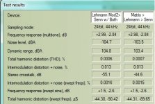
Here are some test results (no further mods yet):
1. Subjective: To eliminate the POT causing issues, I maxed the volume on the Pot and used Digital Attenuation at the source (Foobar WASAPI). Clarity improved a bit, however I noticed a loss in bass 'punch' and a slightly brighter treble (not a good thing with these headphones).
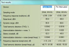
2. I ran some RMAA measurements of before & after mods. And I compared digital and Pot attenuation.
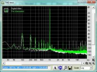
Summary: Before & after mods measurements showed nothing of interest but perhaps that's due to the free version of RMAA which has limited fourier analysis. The -10dB attenuation comparison showed large differences. Almost across the board, digital attenuation was superior. However, THD for some reason was better with the POT (which was approx 50% rotated). Note how my subjective impression above compares to the THD graph... I was perceiving additional low frequency distortion as 'punch'!
PS - The unusual frequency response measurements is due to my EQ settings which compensates for the headphone shortage of sub bass and overly bright low treble.
PSS - These measurements were done with NO gain, level matched with the EMU USB sound card, and the Sennheiser headphone driven in parallel with the external high sound card so distortion is a little higher than amp alone.
Here are some test results (no further mods yet):
1. Subjective: To eliminate the POT causing issues, I maxed the volume on the Pot and used Digital Attenuation at the source (Foobar WASAPI). Clarity improved a bit, however I noticed a loss in bass 'punch' and a slightly brighter treble (not a good thing with these headphones).
2. I ran some RMAA measurements of before & after mods. And I compared digital and Pot attenuation.
Summary: Before & after mods measurements showed nothing of interest but perhaps that's due to the free version of RMAA which has limited fourier analysis. The -10dB attenuation comparison showed large differences. Almost across the board, digital attenuation was superior. However, THD for some reason was better with the POT (which was approx 50% rotated). Note how my subjective impression above compares to the THD graph... I was perceiving additional low frequency distortion as 'punch'!
PS - The unusual frequency response measurements is due to my EQ settings which compensates for the headphone shortage of sub bass and overly bright low treble.
PSS - These measurements were done with NO gain, level matched with the EMU USB sound card, and the Sennheiser headphone driven in parallel with the external high sound card so distortion is a little higher than amp alone.
Attachments
Last edited:
- Status
- This old topic is closed. If you want to reopen this topic, contact a moderator using the "Report Post" button.
- Home
- Amplifiers
- Headphone Systems
- Please technically explain this audible mod