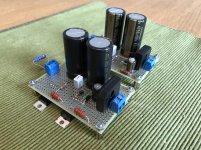
There is a wide range of power supplies you could use. The cap multplier psu I was using for testing
was quite simple but working flawlessly, and best, didn't have an impact on sound. Maybe it could
also be refined some with a pre-regulator?? (thinking out loud)
For the F5 HA I used the so-called Nazar reg that also is very compact, is dead quiet and has relatively
low heat sinking requirements. Shoot me a PM and I can supply you with the schematics.
Please stay away from the Salas shunt regs because they haven proven instable on such a
high bandwidth amplifier and generate too much heat here.
Please stay away from the Salas shunt regs because they haven proven instable on such a high bandwidth amplifier
Really? Never had stability issues with those in dozens of applications...Never had any other regulator even approach them sonically...
Yes, big oscillation with the Salas on the F5HA which cannot be tamed even after adding a 20R power resistor in between.
And we like the Didden regulators more if we have to used ones with low Zout.
(You can also change that to a shunt.)
But everyone chooses what he likes.
Cheers,
Patrick
And we like the Didden regulators more if we have to used ones with low Zout.
(You can also change that to a shunt.)
But everyone chooses what he likes.
Cheers,
Patrick
A question regarding the MOSFET Vgs matching diagram presented in the appendix 4: With the given values of R1=87R and R2=870R I get Idss=0,134V/R1=1,5mA. Should the values be R1=0,134V/8mA=16,75R and R2=167,5R ??? Or is there something that I didn't understand (quite possible)?
While I'm impatiently waiting for my parts to arrive, I've been wondering what would be suitable impedance value for a volume pot? It's beyond my capabilities to derive the input impedance of the UTHAiM from the schematics, so that I could match the pot value for good results. Please enlighten me Patrick.
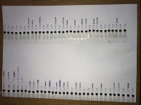
Phew! Now I'm done with the ZVN matching. It took couple of hours, but I think I managed to find quite good quads from the 32 pieces of both P/N channel mosfets.
In the attached picture ZVNs are on the left and ZVPs on the right.
Do you want to do mine as well?
")
When using Exocon laterals instead of Renesas, for best results, you should measure the Vgs of both N & P devices at bias, as well as Yfs.
Using those values, you can adjust the values of R21,22 & R31 accordingly.
https://www.audioasylum.com/cgi/t.mpl?f=critics&m=53009
And since the jumper J31 (or J32, but only one used) carries high current, it is best to use a piece of copper wire instead of a 0R SMD resistor.
Patrick
Using those values, you can adjust the values of R21,22 & R31 accordingly.
https://www.audioasylum.com/cgi/t.mpl?f=critics&m=53009
And since the jumper J31 (or J32, but only one used) carries high current, it is best to use a piece of copper wire instead of a 0R SMD resistor.
Patrick
See attached for a very simple matching circuit for the laterals.
Note polarity differences between N & P MOS.
You can also use this circuit for matching vertical FETs (enhancement mode).
But you will then need to change R11,12 to 10k, and increase supply voltage to 24V.
And make sure you use heat sinks, the larger the better.
Patrick
.
Note polarity differences between N & P MOS.
You can also use this circuit for matching vertical FETs (enhancement mode).
But you will then need to change R11,12 to 10k, and increase supply voltage to 24V.
And make sure you use heat sinks, the larger the better.
Patrick
.
Attachments
- Home
- Amplifiers
- Headphone Systems
- UTHAiM -- Just for Fun