No, thank you for testing the wall wart and giving us feedback on top of sharing with us a wonderful amp design!Analysis of the Adafruit # 2591 +/-12V 500mA wall wart power supply
Here is the promised analysis of the nice +/-12V 500mA wall wart that WoodyLuvr found at Adafruit, their product ID 2591.The summary is that it looks great for audio! Should be a real time-saver in powering some projects, like the Super CMOY here.
In summary: good work, Adafruit, and WoodyLuvr in find this product!
Please kindly help me troubleshoot. This is in regards to Parallel V1.2 version. When I plug in the headphones only the right channel is heard.
On the output jack: If I slowly push in the headphone plug the sound initially is in the left channel only but when the plug is fully inserted it switches to the right channel.
On the input jack: If I slowly pull out the line input jack to half way out the sound goes away completely.
PCB INPUT PIC
If I connect the left and right input channels directly (though mono) as shown in the pic above I then have both left and right channels in my headphones so the amp circuit is fine, as well as the output headphone jack.
I wonder if I might have heat damaged the left channel of/on the input jack when I desoldered it from the PCB board???
Last edited:
Thanks for the nice test of the +/-12v wallwart. That is indeed handy to have around.
I send the small CMOY style PCBs taped inside a folded sheet of paper so it feels like paper. Have not gotten any rejections when using international forever stamp ($2 and change). If you send in small padded envelope with Fist Class International via PayPal postal label, it is $3.40 I think. Has tracking to boot but doesn't track well after leaves US, until reaches the "last mile" post office. Takes 3weeks to 5wks sometime for certain countries. Whereas the "paper mail" is no more than 10 days.
xrk971 - I haven't had any luck here (Texas) with sending PC boards in a standard envelope. The postal clerks always note (I've tried it several times) they are "unbendable", which is postal parlance means "not machinable". The Post Office can't run them through letter sorting machines at the sorting centers, have to be sorted by hand. So they have to go "international small parcel" which is $14. Hey any tricks you have here, please share!! $14 is ridiculous to send a tiny PC board. I wish the USPS had a "small package" rate, like Canadian Post does, something half the cost of $14.
I send the small CMOY style PCBs taped inside a folded sheet of paper so it feels like paper. Have not gotten any rejections when using international forever stamp ($2 and change). If you send in small padded envelope with Fist Class International via PayPal postal label, it is $3.40 I think. Has tracking to boot but doesn't track well after leaves US, until reaches the "last mile" post office. Takes 3weeks to 5wks sometime for certain countries. Whereas the "paper mail" is no more than 10 days.
Hey guys!
Just letting everyone know AGDR got back to my email and has really gone above and beyond answering all my questions and even supplying some parts in his shop that were out of stock from vendors. I received the PCBs, TPS boards, and the Bourns pots from him in the mail very quickly and everything was packaged to withstand a trip down an elevator shaft
Right now I'm building one of the single chip versions into an aluminum enclosure a little larger than the mint tin (103 x 75 x 34.5mm)
I'm still in the design phase, but WoodyLuvr taking AGDRs suggestion of converting it to be USB powered was too tempting to pass up, so I grabbed one of the Recom modules from Mouser.
One point of confusion I'm having is I can't see anywhere in the datasheet about heat-sinking other than this brief mention in the description:
"The RW_D series with 2:1 input voltage ranges and maximum height of 7,0 mm has been designed for industrial automation and medical markets where a dual output rail needs to be generated from a single rail source. The converters supply the full 3 Watts without additional heat-sinks over the temperature range -40°C to +85°C. "
I'm wondering if I mount the module on a perf board with some space around it, would it still be necessary to add a heat sink? Just how warm does it get?
I can totally mount it to the enclosure with some thermally conductive RTV to the chassis if beneficial, but it would make it more of a pain for tweaks/disassembly
Have you considered just using a slim, low-profile heat sink with an adhesive back? That is what I am doing so that the power module can be easily moved and/or worked on. The fins will simply rest on your case bottom and that way even more heat will dissipate from the RECOM DC-DC converter stuck to the adhesive side of the heat sink....One point of confusion I'm having is I can't see anywhere in the datasheet about heat-sinking other than this brief mention in the description:
"The RW_D series with 2:1 input voltage ranges and maximum height of 7,0 mm has been designed for industrial automation and medical markets where a dual output rail needs to be generated from a single rail source. The converters supply the full 3 Watts without additional heat-sinks over the temperature range -40°C to +85°C. "
I'm wondering if I mount the module on a perf board with some space around it, would it still be necessary to add a heat sink? Just how warm does it get?
I can totally mount it to the enclosure with some thermally conductive RTV to the chassis if beneficial, but it would make it more of a pain for tweaks/disassembly
Here are a few models that are even thinner than the 40 x 40 x 9.5 mm model that I purchased and planning to use:
30 x 30 x 6.3 mm
40 x 40 x 6.3 mm
35 x 35 x 7 mm
Hope this helps.
Thanks WoodyLuvr!
That's definitely helpful. I may end up going that route. And I'd love to see some pictures of your amp when you get it all finished!
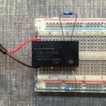
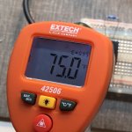
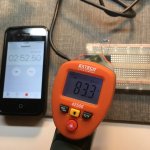
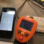
For kicks, I did some very crude thermal testing of the Recom on a breadboard powering it off a 2.4 amp Apple phone charger with the 499 ohm resistors connected. Here were my results using an infrared thermometer measuring the max temperature of the Recom and resistors as a whole. From what I could tell - to the touch, the resistors were the main source of heat. The Recom seemed to barely get warm...
Before power applied: 75°F
02:33 - 83.0°F
02:52 - 83.3°F
03:01 - 84.3°F
03:18 - 85.8°F
03:58 - 86.0°F
04:20 - 86.7°F
04:27 - 87.0°F
04:30 - 87.4°F
04:45 - 88.3°F
05:06 - 88.8°F
05:11 - 89.6°F
05:48 - 89.9°F
05:59 - 90.1°F
06:07 - 90.6°F
09:37 - 96.0°F
I about have my first single chip Super Cmoy finished, but Mouser and Digikey were out of the IM26TS relays, with a 54 week lead-time
Thankfully, once again AGDR saved the day and had some in his shop that he just mailed me
That's definitely helpful. I may end up going that route. And I'd love to see some pictures of your amp when you get it all finished!
For kicks, I did some very crude thermal testing of the Recom on a breadboard powering it off a 2.4 amp Apple phone charger with the 499 ohm resistors connected. Here were my results using an infrared thermometer measuring the max temperature of the Recom and resistors as a whole. From what I could tell - to the touch, the resistors were the main source of heat. The Recom seemed to barely get warm...
Before power applied: 75°F
02:33 - 83.0°F
02:52 - 83.3°F
03:01 - 84.3°F
03:18 - 85.8°F
03:58 - 86.0°F
04:20 - 86.7°F
04:27 - 87.0°F
04:30 - 87.4°F
04:45 - 88.3°F
05:06 - 88.8°F
05:11 - 89.6°F
05:48 - 89.9°F
05:59 - 90.1°F
06:07 - 90.6°F
09:37 - 96.0°F
I about have my first single chip Super Cmoy finished, but Mouser and Digikey were out of the IM26TS relays, with a 54 week lead-time
Thankfully, once again AGDR saved the day and had some in his shop that he just mailed me
Attachments
Thank you for sharing that temp test. Running very cool. Not surprised though as the converter was designed for medical instruments. In the RECOM datasheet it states: "The converters supply the full 3 Watts without additional heat-sinks over the temperature range -40°C to +85°C." so I am using the heatsink more as a platform to build the power module upon rather than "cooling" peace of mind ;-)Thanks WoodyLuvr!
That's definitely helpful. I may end up going that route. And I'd love to see some pictures of your amp when you get it all finished!
For kicks, I did some very crude thermal testing of the Recom on a breadboard powering it off a 2.4 amp Apple phone charger with the 499 ohm resistors connected. Here were my results using an infrared thermometer measuring the max temperature of the Recom and resistors as a whole. From what I could tell - to the touch, the resistors were the main source of heat. The Recom seemed to barely get warm...
Before power applied: 75°F
02:33 - 83.0°F
02:52 - 83.3°F
03:01 - 84.3°F
03:18 - 85.8°F
03:58 - 86.0°F
04:20 - 86.7°F
04:27 - 87.0°F
04:30 - 87.4°F
04:45 - 88.3°F
05:06 - 88.8°F
05:11 - 89.6°F
05:48 - 89.9°F
05:59 - 90.1°F
06:07 - 90.6°F
09:37 - 96.0°F
I about have my first single chip Super Cmoy finished, but Mouser and Digikey were out of the IM26TS relays, with a 54 week lead-time
Thankfully, once again AGDR saved the day and had some in his shop that he just mailed me
Surely good sir. I will post pics on this thread when complete. However, it is going slowly. I am still working on the case and once that is complete I will then build the DC/DC power module and then connect it up. Do kindly share your RECOM DC-DC converter build when complete.
Indeed. Martin (AGDR) is an extremely helpful fellow. I am as well very appreciative of his, as well as Alex's (adydula) expertise and kindness.
Last edited:
Hey guys,
I am from Europe and I cannot find the IM26TS on any website I know. Does anyone know a good replacement part? Or perhaps a website that has them on stock? ( would rather not get it from ebay or the like.. )
RS Components has them, part number 515-527
RS Components has them, part number 515-527
Thank you very much! Ordered!
adydula has touched upon this a few times back in this thread... here are a few that I can find immediately:Just out of curiosity, are there any objective tests to say which one of the O2 or Super Cmoy that measures best? Listening reviews tends to be a bit subjective, although a comparison test would be nice.
Post 145
Post 151
Post 7
Post 245
Last edited:
Thanks! Well, being a very happy user of an original CMoy + TLE2426 virtual ground mod I made myself on veroboard a few years back I would belive there is great step up in this upgrade. Been using it with a pair of Koss Porta Pro and a grubDAC at work. A really nice combo.adydula has touched upon this a few times back in this thread... here are a few that I can find immediately: ...
Will probably order a Super Cmoy kit rather soon and combine it with an ODAC.
...and some better headphones as well.
Found this on Jamecos homepage. Would work nicely?
JE215: Jameco Kitpro : Dual-Output Adjustable Linear Regulated Power Supply Kit : Electronic Kits & Projects
JE215: Jameco Kitpro : Dual-Output Adjustable Linear Regulated Power Supply Kit : Electronic Kits & Projects
Found this on Jamecos homepage. Would work nicely?
JE215: Jameco Kitpro : Dual-Output Adjustable Linear Regulated Power Supply Kit : Electronic Kits & Projects
Interesting. I wonder if the minimum 175 mA per supply would still be to much???
IT'S ALIVEEEEE!!!!!!!
I have finally completed building a USB-Powered desktop variant of agdr audio's opa1688 parallel super cmoy and it is performing perfectly!
The RECOM RW-0509D DC-DC Converter is running very cool... surprisingly and pleasantly so! Probably didn't need the heat sink and insulation pad but better safe than sorry I say!
I will need to wait until tomorrow to post pictures as I am forbidden to touch my wife's digital camera :-(
Anyhow, she'll take better pictures than I ever could.
Many thanks to all on board who have helped me with the build!
Last edited:
agdr audio opa1688 parallel super cmoy; usb-powered desktop version
Only waiting on one final part to arrive... a 19mm wide brass volume knob.
Please kindly excuse the shotty soldering and gluing... I battle severe hand tremors.
FACE (FRONT SIDE)
THE GUTS (INSIDE)
BACK SIDE
LEFT SIDE
RIGHT SIDE
TOPSIDE
UNDERSIDE
RECOM RW-0509D DC-DC CONVERTER POWER SUPPLY MODULE-PIC 1
RECOM RW-0509D DC-DC CONVERTER POWER SUPPLY MODULE-PIC 2
Only waiting on one final part to arrive... a 19mm wide brass volume knob.
Please kindly excuse the shotty soldering and gluing... I battle severe hand tremors.
FACE (FRONT SIDE)
An externally hosted image should be here but it was not working when we last tested it.
THE GUTS (INSIDE)
An externally hosted image should be here but it was not working when we last tested it.
BACK SIDE
LEFT SIDE
RIGHT SIDE
TOPSIDE
UNDERSIDE
RECOM RW-0509D DC-DC CONVERTER POWER SUPPLY MODULE-PIC 1
RECOM RW-0509D DC-DC CONVERTER POWER SUPPLY MODULE-PIC 2
Last edited:
Regarding WoodyLuvr's use of an isolated DC DC Boost regulator. Why is isolated important in this context? There are a number of non-isolated DC/DC boost converters out there that canb do +/-9V, eBay has quite a few. As long as we have an output of the connection inbetween, we have a "real ground" that can be used. Just as for the split supply from adafruit.
Regarding WoodyLuvr's use of an isolated DC DC Boost regulator. Why is isolated important in this context? There are a number of non-isolated DC/DC boost converters out there that canb do +/-9V, eBay has quite a few. As long as we have an output of the connection inbetween, we have a "real ground" that can be used. Just as for the split supply from adafruit.
Here is the thread in which agdr introduces the RECOM DC-DC Converter. All comes down to "noise" thus the reason why agdr was so interested in testing the adafruit split dc power supply that I had stumbled upon and mentioned in a post way back when.
Last edited:
- Home
- Amplifiers
- Headphone Systems
- OPA1688 Super CMOY, 2x 9V with real ground and headphone relay - PCBs