New BOM revision - gain resistor choices and connection pin #
Good point, in fact I've just made a new BOM revision to include some choices for the gain resistors. Attached below and also out at the project Google Drive link. I've grouped the resistor choices a bit better for 3 typical voltage gains: 1x, 2x, and 4x.
For 1x the standard thing to do is jumper the feedback resistors R11 & R12 (jumper wires instead of resistors for those pads) and then no need to install the 47pF caps C7 & C8. R8 & R9 are left unpopulated.
I'm just curous about johnc124's take on it given that he posted in the vendor forum thread that he did a bit of testing to settle on the 47pF for maximum stability with larger capacitive loads. Pretty slick being able to converse with someone who worked on the design of the chip.")
In the new BOM I've also added the part number for the adapter board pluggable connection pins for completeness, although I supply those with the adapter board if anyone gets it from me.
The OPA1688 does seem like the perfect chip for a CMOY! Low battery drain yet high output current and great THD+N. As popular as CMOY headamps have been I'm surprised it has taken manufacturers so long to come up with an appropriate headphone driver chip.
An interesting thing to me is how much peripheral "stuff" is required to support an amp chip. RF filter, DC blocking caps. Without the SSR power management circuit it would be back to a virtual ground, which in turn would probably negate much of the chip's low THD+N and add crostalk. I've done a spice simulation with a OPA1688 acting as a virtual ground for another OPA1688 and the sim worked just fine. But an active VG always adds some "trash", as per NwAvGuy's famous VG analysis:
http://nwavguy.blogspot.com/2011/05/virtual-grounds-3-channel-amps.html
Then there is the problem that a VG really needs to be able to sink/source 2x the current of either channel, so both channels can be returned to it and still run at full current output. Which in turns always implies the VG needs to be a different chip, or the amplifier chip needs to settle on running at just half the rated current drive. I tried using one of the new OPA1622's as a VG in the simulation but the sim just locked right up with that one. Best to avoid the issue entirely and use the real ground if possible!
Then there is the headphone relay. I did try the OPA1688 without a relay and there was some turn-on turn-off thump. Not huge, but audible. Interestingly going from just a DPDT toggle switch for the power rails in V1.0 of the CMOY to the solid state relays in V2.0 helped reduce the thump considerably, even without the output relay. The benefits of having the rails go up & down in unison, as much as possible.
And that is the current V4.0 here that adydula is working on now! I'll be curious to see how your case comes out. You do such a good job with the hole marking and drilling. Plus listening impressions like johnc124 said! I know you have all my amp designs there plus some others.
Just chipping in here to say I'm interested in setting up mine with a gain of 1, I was going to ask after ordering the boards, but since it's already come up...
Good point, in fact I've just made a new BOM revision to include some choices for the gain resistors. Attached below and also out at the project Google Drive link. I've grouped the resistor choices a bit better for 3 typical voltage gains: 1x, 2x, and 4x.
For 1x the standard thing to do is jumper the feedback resistors R11 & R12 (jumper wires instead of resistors for those pads) and then no need to install the 47pF caps C7 & C8. R8 & R9 are left unpopulated.
I'm just curous about johnc124's take on it given that he posted in the vendor forum thread that he did a bit of testing to settle on the 47pF for maximum stability with larger capacitive loads. Pretty slick being able to converse with someone who worked on the design of the chip.
In the new BOM I've also added the part number for the adapter board pluggable connection pins for completeness, although I supply those with the adapter board if anyone gets it from me.
Looks very interesting.
The OPA1688 does seem like the perfect chip for a CMOY! Low battery drain yet high output current and great THD+N. As popular as CMOY headamps have been I'm surprised it has taken manufacturers so long to come up with an appropriate headphone driver chip.
An interesting thing to me is how much peripheral "stuff" is required to support an amp chip. RF filter, DC blocking caps. Without the SSR power management circuit it would be back to a virtual ground, which in turn would probably negate much of the chip's low THD+N and add crostalk. I've done a spice simulation with a OPA1688 acting as a virtual ground for another OPA1688 and the sim worked just fine. But an active VG always adds some "trash", as per NwAvGuy's famous VG analysis:
http://nwavguy.blogspot.com/2011/05/virtual-grounds-3-channel-amps.html
Then there is the problem that a VG really needs to be able to sink/source 2x the current of either channel, so both channels can be returned to it and still run at full current output. Which in turns always implies the VG needs to be a different chip, or the amplifier chip needs to settle on running at just half the rated current drive. I tried using one of the new OPA1622's as a VG in the simulation but the sim just locked right up with that one. Best to avoid the issue entirely and use the real ground if possible!
Then there is the headphone relay. I did try the OPA1688 without a relay and there was some turn-on turn-off thump. Not huge, but audible. Interestingly going from just a DPDT toggle switch for the power rails in V1.0 of the CMOY to the solid state relays in V2.0 helped reduce the thump considerably, even without the output relay. The benefits of having the rails go up & down in unison, as much as possible.
Got parts, got boards, iron is getting hot!! LoL
And that is the current V4.0 here that adydula is working on now!
I'll be curious to see how your case comes out. You do such a good job with the hole marking and drilling. Plus listening impressions like johnc124 said! I know you have all my amp designs there plus some others.Attachments
Last edited:
Hey great shots!!! I like the tape method!!! (lol).....Simple things for simple minds...
I am starting to populate this morning!
The version 3.0 that I built is still working very well and sounds very good. I compared to many amps and was pleasantly surprised how well it holds up. Actually to be brutally honest except for the gobs of power other amps might have, the actual real world hearing differences are very small....
In other words I think I could fool most people in a AB blind test most of the time! This is with most headphones that are fairly sensitive. Cans like the "HE" stuff are a different beast.
Its really great to see a company like TI develop a chip for the headphone market!!! So far its working out very, very well!..
I will post my results with V4 soon.
Alex
I don't know where this question comes from because planar magnetic headphones are usually almost purely resistive loads, the easiest load for amps.Can it drive planar headphone with solid bass?
Or do you just mean low sensitivity and low impedance headphones?
It shouldn't be that hard to calculate ideal gain given your source, headphones and target peak SPL, and therefore voltage/current needed.
I can not wait how good this cmoy is ?
Can it drive planar headphone with solid bass?
I might pushing to much ?
How much total kit cost?
Please post your headphone brand and model number, or impedance & sensitivity rating, and I'll feed the numbers to a SPL spreadsheet.
The current BOM totals up to $39.75 US dollars for the parts at Mouser using the lower-cost option for the SSR (0.0625 ohms on). For the Coto CT128 SSR with the 0.0125 ohms "on" add $8 to that (those chips are $6.30 each at Mouser). Then you need the PC board and adapter board. The $39.75 assumes you are soldering your own adapter. For a fully assembled TPS3701 adapter you don't need the TSP3701 chip, adapter PC board, or 0.1uF 0603 cap in the BOM, and then add $8.50 for the assembled adapter.
With throw-away 9V batteries (primary cells) or NiMH "9V" rechargeable batteries the power management circuit would be set to cut off at +/-7Vdc for the low battery level (same as in NwAvGuy's O2 headphone amp). The OPA1688 is rail-to-rail output, so that will give a maximum swing of 7Vdc peak, or 4.95Vrms.
Lets do a double-check on current levels at that minimum-battery-level voltage swing number. Peak current into 16R headphones would be 7Vdc/16R = 44mA, rms average would be 4.95Vrms/16 = 31mA(rms). Both are just fine for the 75ma-per-channel OPA1688. In fact, multiplying that chip maximum by 2 for 2 channels, both the batteries and the solid state relays have no problems suppling the full 150mA. The SSRs are rated at 4.5A for the Coto and 2A for the Vishay.
On the other end of things, with fully charged batteries, rather remarkably everythng is still just fine! "9V" NiMH cells can go up to 11.0Vdc right off the charger. The peak current there into 16R cans would be 11.0Vdc/16R = 69mA, rms average = 7.78Vrms/16R = 49mA(rms). All still OK for the 75mA/channel OPA1688! Headphone with higher impedances would be even lighter loads of course, like 32R, and even easier for the OPA1688 to drive.
If anyone goes into the chip power dissipation calculations remember to take "music power" into account vs. sine wave testing, where the votlage peaks in actual music are typically 2x to 3x the average levels.
So in summary this little OPA1688 Super CMOY really can drive 16 ohm and up headphones with no trouble at any charge level for the two "9V" batteries. Try that with a OPA2134 chip and rail splitter in a conventional CMOY.
As for how it sounds, lets get some listening reports in from Adydula and the other folks building it up.
But here is one in another thread regarding OPA1688 bass from borges where he was asking about various headphone chips vs. his existing NJM4556A. I had suggested trying the OPA1688, which he did (post 19):http://www.diyaudio.com/forums/headphone-systems/291981-op-amp-headphones.html#post4742978
I was commenting in there that for some reason that I have never been able to figure out the NJM4556A seems "bass challenged" to me. I never have been able to find any electrical reason for that. NwAvGuy tested the heck out of his O2 Headamp (which uses paralleled NJM4556A chips in the output stage), all posted on his blog. The frequency response is flat down to 20Hz and the distortion is low at 16R. Yet my ears have always said "bass problem", especially when running on the lower battery voltages vs. AC rails. Go figure!
Last edited:
That only makes sense if the NJMs are unhappy with inductive/capacitive loads (below and above resonant frequency of dynamic headphones) with low supply voltages.The frequency response is flat down to 20Hz and the distortion is low at 16R. Yet my ears have always said "bass problem", especially when running on the lower battery voltages vs. AC rails. Go figure!
Yet another BOM revision!
I have yet another BOM revision attached below and posted out on the project Google Drive link.
A big thanks to Adydula for finding two BOM omissions during his build! I left off the diodes D5 and D6 that go across the relay coil to suppress the reverse voltage surge. Those diodes are on the board and schematic, I just left them off the BOM.
I've also realized that the 9.6Vdc volt version of the "9V" NiMH rechargeable batteries (the maha energy Powerex battery in the BOM) will have a 8.0Vdc cutoff, rather than the 7.0Vdc cutoff for standard 8.4Vdc "9V" NiMH cells. I've added a set of resistors for R3, R4, and R5 to cover that case. I've re-grouped all the R3, R4 and R5 resistors to make the choices clearer. There are now 3 sets of those resistors to handle the 3 different battery types:
* A set of R3, R4 and R5 values for the 7.0Vdc low battery cutoff level of throw-away primary batteries and standard 8.4Vdc "9V" NiMH rechargeable batteries.
* A set of R3, R4 and R5 values for the 8.0Vdc low battery cutoff level of the maha Powerex 9.6Vdc "9V" NiMH rechargeable batteries.
* A set of R3, R4 and R5 values for the 6.27Vdc low battery cutoff level of 7.4Vdc "9V" lithium ion rechargeable batteries.
And a follow-up note on my post above. Where the 11Vdc comes from for a maximum power supply level is that same 9.6Vdc "9V" maha Powerex NiMH rechargeable. NiMH cells are 1.2Vdc nominal and around 1.4Vdc per cell right off the charger. The 9.6Vdc battery is an 8-cell unit, so 8 * 1.4Vdc = 11.2Vdc. The standard 8.4Vdc "9V" NiMh 7-cell battery would have a maximum voltage off the charger of around 7 * 1.4Vdc = 9.8Vdc.
I have actually seen 8.4V nominal "9V" NiMH cells charge up to around 1.45V per cell, which is around 10.15V off the charger. Apply that to the 9.6v Powerex cells gives a maximum off-the-charger voltage of 11.6Vdc, so +/-11.6Vdc power rails at that point in the Super CMOY. For a 16 ohm headphone load that gives 11.6Vdc/16 = 72.5mA, still within the OPA1688's 75mA.
Attachments
Last edited:
That only makes sense if the NJMs are unhappy with inductive/capacitive loads (below and above resonant frequency of dynamic headphones) with low supply voltages.
I don't have any objective explanation for it at all - purely a subjective thing, which I know would make NwAvGuy's head explode, wherever he is out there.
And it may just be me, too. I've made the comment about the NJM4556A a couple of times over the years in posts about the O2 headamp and other folks have posted that they don't hear a bass problem at all with the O2/NJM4556A. So.. YMMV. This is the link:
https://www.audeze.com/products/lcd-collection/lcd2
Style Open circumaural
Transducer type Planar magnetic
Magnetic structure Proprietary push-pull design
Magnet type Neodymium
Transducer size 106 mm
Maximum power handling 15W (for 200ms)
Sound pressure level >130dB with 15W
Frequency response 5Hz – 20kHz extended out to 50kHz
Total harmonic distortion <1% through entire frequency range
Impedance 70 ohms
Efficiency 101dB / 1mW
Optimal power requirement 1 – 4W
This is the link:
https://www.audeze.com/products/lcd-collection/lcd2
Good news - the Super CMOY here would work just fine with your LCD-2's! In fact the Super CMOY has way more maximum power capability than you would require.
I've attached the LCD-2 vs. Super CMOY Sound Pressure Level spreadsheet below as a PDF. I've also created a new folder out on the project Google Drive link for these spreadsheets for varous headphones. Here I'm just posting the pdf's to make it easy to read, but on the Google Drive I'll also post the raw spreadsheet file for each, in case anyone wants to mess with the numbers themselves.
So lets walk through the numbers! This spreadsheet was posted by Rob Robinette on Head-Fi a while back. Right off the bat the spreadsheet requires that a target Sound Pressure Level be entered. For years I've always used 120dB, which is as loud as a freight train, to cover those peak instantaneous passages in music. Scroll down on that spreadsheet and in the bottom half Rob has a loudness chart. 120dB is the "7 minutes maximum exposure" level. But in actual practice it would be extremely rare to have any music burst that loud, and if it did it would be for a fraction of a second. But I'm a guy who designs for worst-case scenarios, so I use 120dB.
Or at least I used to.
When johnc124 first posted his new OPA1688 and OPA1622 chips on the vendor forum here I instantly dismissed them over this issue. He was claiming the chips worked with a wide range of headphones, but I knew from past experience some of those couldn't get to 120dB with the capabilities of the two chips. Some discussion ensued and it turns out johnc124 and TI were targeting just 90dB maximum SPL, as I recall. In thinking about that whole issue some more I've more or less decided he is right, or at least something in the middle. For a dB (log) scale that might be 110dB.But regardless, your LCDs could, in fact, hit 120dB with the Super CMOY! They could even go up to a 128dB peak with the volume all the way up, and that is with average (nominal) battery levels.
The first line on the spreadsheet inputs the impedance of the headphones, which in this case is 70 ohms. The next two are sensitivity of the headphones, either in db/mW (= per 1 mW), OR in dB/V. Only one or the other is used, whichever the manufacturer gives. Rob has the spreadsheet set up so that you put a 0 in the field for the one not being used. The LED-2's are 101dB/mW, so that goes in field #2 and the 0 goes in field #3 for dB/V.
Then down to the next yellow entry field, the target dB loudness, we enter the 120dB SPL (sound pressure level). That is all the information you need for the spreadsheet to then calculate and fill in the various number results, but the final yellow entry field is worth filling in too. That is the maximum power the amp is capable of with the headphones. That he field needs the amplifier's maximum RMS voltage swing. Here I've used 5.95Vrms, which equates to 8.4V peak, the amount you get with the average (nominal) voltage of "9V" NiMH rechargeable cells.
So lets look at the results! In the second field below that 120dB entry field you have the rms voltage swing required to hit the 120 dB SPL level. It calculated 2.35V(rms). Now compare that with my rantings in post #26 above, where I calculated the rms output of the Super CMOY with nearly dead batteries is 4.95V(rms). That is the point where the power management circuit is about to cut the batteries off.
Even with nearly dead batteries the Super CMOY could supply about 2 volts more than you need to hit the whopping huge 120dB SPL with the volume all the way up. Then the line below that is the current required, per channel, at that 2.35Vrms level, 33mA. 33mA is 46mA peak, and the OPA1688 is good for 75mA peak. Once again, plenty of headroom.
I've posted a second spreadsheet below done at the much lower level of 100dB SPL for peaks. That would most likely be a closer match to real listening - an average of 80dB SPL with peaks up to 90 or 100, as per what johnc124's design goals appear to be. At that level you only need 0.23Vrms and 3.37mA of current. Two things to consider here! One is you probably don't need voltage gain. You would want to wire the amp up for the 1x voltage gain (current buffer only) option in the BOM. The other is that your batteries will last a long time with that low level of current draw. In fact, if you used lithum batteries (I'll answer your other post next, good question there) I'll bet you could go a week of 8 hour days on two "9V" lithium cells.
Attachments
Last edited:
Btw, does anyone try using 18650 type battery ?
Better sound quality ?
Yeah those are the batteries used in laptop battery packs and are pretty large. The similar thing you would want to consider using with the Super CMOY are lithium ion (or lithium polymer) "9v" (actually 7.4V nominal) batteries, like these:
2 Bank 9 Volt Battery Charger with 2 Batteries: BatteryMart.com
From the calculation I just did in the post above, I'll take a guess that at normal listening levels two of these lihitum batteries would last a whole week's worth of 8 hour days with your LCD-2's!
As for how the batteries affect that sound, that is a really good question. In the vendor thread that came up once and I believe johnc124 mentioned he had measured either primary cells or NiMH (can't remember which now) and found the internal resistance was 2 or 3 ohms, as I recall. That surprised me, that numbers I had heard in the past were an ohm or less.
I've seen other posts in the past with folks saying lithium batteries have a lower internal resistance than other types.
Well this is such a good question I would say it is time to do some measuring! I'll do that as time permits, although it may be a week or two before I can get around to it. I want to find out exactly what the internal resistance of primary cells (a Duracell 9V for the local grocery store), a "9V" 8.4V NiMH and one of the lithium polymer cells are.
In case someone out there has some time and beats me to it, here is how to do that test.
The battery is modeled as and ideal voltage source in series with an internal resistor that you can't see. First measure the value of the ideal voltage source by measuring the voltage of the battery with nothing connected. Since there is no current flow through the internal resistor it has no voltage drop, meaning what you measure is just the ideal voltage source level.Then grab a power resistor, any value, but something around 100 ohms may be a good start. It should be 2W or 5W since we are going to dump a lot of the battery's energy into that resistor. Measure the voltage across the power resistor while you attach it to the "9V" battery. What we want here is a value of the resistor that causes the battery output votlage to drop a bit, something measureable, say something in the range of 0.2Vdc to 0.5Vdc or so. If 100 ohms doesn't do it try a 50 ohm power resistor instead.
So an example. Lets say the open circuit voltage of the battery mesured 9.20V. Then lets say your 100 ohm resistor dropped that to 9.00 volts. The current through the power resistor, battery ideal voltage source, and the mystery resistor inside the battery is 9.0V/100 ohms = 90mA. But we also know the voltage across that internal mystery resistor! Since the open circuit voltage was 9.2, and now the output is 9.0, that internal battery resistor has 0.2V across it.
The value of the mystery internal battery resistance would then be 0.2V / 90mA = 2.2 ohms.
This is all at DC (0 Hz) of course. Things might change a bit at higher audio frequencies since that resistance is likely an impedance, but for now this will be a pretty useful model.
Last edited:
2.2 Ohms isn't far off from my own measurements so its good to see this confirmed by at least one other source.
As to your earlier resistor question, there really is no one answer for feedback resistor values. If the resistors are made too large, they interact with the input capacitance of the op amp and can cause stability issues. If they are too small then they obviously draw excessive amounts of current. One rule of thumb I've used before is to keep the thermal noise contribution from the resistors less than 1/3rd the input voltage noise of the op amp, that way they do not appreciably increase the total noise of the system. Assuming about an 8nV/rtHz broadband noise for the OPA1688, that would suggest that the parallel combination of the feedback resistors should be about 430 ohms or less. So for a gain of 2, that would be feedback resistor values of 860 ohms each or the closest value in your desired tolerance.
This is less than your selected values of 2k/2k, but like I said before there's no right answer. In a real world application (e.g. playing music) I'm skeptical of how much power is actually wasted in the feedback resistors since the output of the op amp will spend most of its time far away from either power supply rail.
Sorry for the short reply to a long question. I'm living on the road at the moment and don't have much time for audio fun Hopefully that will change soon and I can get back to engineering!
As to your earlier resistor question, there really is no one answer for feedback resistor values. If the resistors are made too large, they interact with the input capacitance of the op amp and can cause stability issues. If they are too small then they obviously draw excessive amounts of current. One rule of thumb I've used before is to keep the thermal noise contribution from the resistors less than 1/3rd the input voltage noise of the op amp, that way they do not appreciably increase the total noise of the system. Assuming about an 8nV/rtHz broadband noise for the OPA1688, that would suggest that the parallel combination of the feedback resistors should be about 430 ohms or less. So for a gain of 2, that would be feedback resistor values of 860 ohms each or the closest value in your desired tolerance.
This is less than your selected values of 2k/2k, but like I said before there's no right answer. In a real world application (e.g. playing music) I'm skeptical of how much power is actually wasted in the feedback resistors since the output of the op amp will spend most of its time far away from either power supply rail.
Sorry for the short reply to a long question. I'm living on the road at the moment and don't have much time for audio fun
Hopefully that will change soon and I can get back to engineering!That's a ... good long answer.
I would like to have all the component and the pcb if everything is done.
But I don't see options using 18650 battery? Since I have lotta them.
I wonder if I can use 3 x 18650 for each rail? Which is 4.2x3=13.6 max.
Is it better in term of SQ compare to just using 2 x 18650 ?
I would defenetly using 18650 for this.
Please PM me.
That's a ... good long answer.
I would like to have all the component and the pcb if everything is done.
But I don't see options using 18650 battery? Since I have lotta them.
I wonder if I can use 3 x 18650 for each rail? Which is 4.2x3=13.6 max.
Is it better in term of SQ compare to just using 2 x 18650 ?
I would defenetly using 18650 for this.
Please PM me.
Good deal, I'll send you a PM.
In general though, regarding the 18650s, you could certainly use those but you would have to get a bigger case of some kind, of course. The Super CMOY board mounts via the front panel parts, the nuts on the pot and two 3.5mm jacks. You could make those same 3 holes in any case you want, then run wires from the battery wire holes on the Super CMOY board to your 18650 battery holders.
Yet another great thing about the OPA1688 is the low THD+N numbers are specified for the entire voltage range, from +/-2.25Vdc to +/-18Vdc. Many op-amps are THD+N specified at just one voltage sweet spot, usually whatever the datasheeet spec tables are done at, like +/-15Vdc. So that means it wouldn't matter if you used just two 18650s for +/-3.7Vdc nominal, or four for +/-7.4Vdc nominal, or 6 for +/-11.1Vdc nominal, you get the same great THD+N numbers.
Since 18650's are rechargeable lets do a check on the whole voltage range. 3.7Vdc is nominal (average) but they go from around 3.3Vdc where the internal protection chip (if they have one, recommended!!) cuts off, to the 4.2Vdc fully-charged cutoff. On the low side, with just two 18650s, that would be +/-3.3Vdc, but I have SB140 Schottky polarity protection diodes (vf=0.18 at these current levels) in series with the battery input, so it would actually be 3.3Vdc - 0.18Vdc that the OPA1688 "sees", or +/-3.12Vdc. The SSR voltage drop can be ignored with its tiny 0.0125R "on" resistance. +/-3.12Vdc is still well above the OPA1688 minimum of +/-2.25Vdc, so all is well on the low end here.
On the high end, three 18650s right off the charger would be 3 x 4.2Vdc = 12.6Vdc and I'll ignore the Schottky voltage drop on this one. +/-12.6Vdc (six 18650s) would still be well under the OPA1688 maximum of +/-18Vdc. So the high(er) voltage end works too.
Last edited:
Assuming about an 8nV/rtHz broadband noise for the OPA1688, that would suggest that the parallel combination of the feedback resistors should be about 430 ohms or less. So for a gain of 2, that would be feedback resistor values of 860 ohms each or the closest value in your desired tolerance.
Thank you for the feedback!
Good point about the average AC voltage excursions being (well) below the peak ("music power") and therefore reducing the AC current draw by the feedback parts. I hadn't considered that! Well then, sold.
I'm going to make a BOM change to reduce the feedback resistors to 1K from the existing 2K, or multiples of 1K for higher gains than 2. I'm going with 1K just as being a standard and common part value, plus Mouser has 1/8W sized 1K's in 0.1% (for cheap too, $0.54 each), which will help with channel-to-channel gain match.This change will be yet-another improvement (in Johnson/therrmal noise) over NwAvGuy's O2 headphone amp. He used 1.5K for the gain stage feedback resistor, likely because the NJM2068 used in the gain stage is only THD specified in its datasheet for a minimum 2K load. The "high gain" resistor to ground was 274R, which would result in nearly 2K, 1.5K + .274K = 1.77K. No such current-drive problem with the OPA1688, so might as well take advantage of the ability to drive the lower resistance feeback parts!
I'm living on the road at the moment and don't have much time for audio fun
You need a CMOY for those road trips!
Last edited:
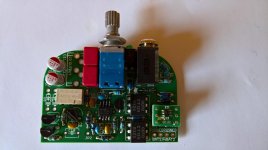
It took me a little less than 2 hours, I am slow and methodical, I use a schematic, check parts with a meter, make sure its the correct part in the correct spot..easy than having to remove! Then install and use a yellow highlighter to mark on the schematic to keep track and that all parts are indeed installed.
Another hour working on making the holes in the Altoid can, its a fragile can with thin material, slow and easy.
Heres a pix, just one switch to install and 2 zeners then test time!
Alex
Another hour working on making the holes in the Altoid can, its a fragile can with thin material, slow and easy.
Heres a pix, just one switch to install and 2 zeners then test time!
Alex
Attachments
Revised BOM, new 1x 2x 3x 4x voltage gain resistors
As per my post #37 above I've updated the BOM with some new gain resistor sets for 1x, 2x, 3x, and 4x voltage gain. The new BOM is attached below and also posted out at the Google Drive link.
HOWEVER, since posting above it hit me that using 0.1% gain resistors would be pointless since the pot is 10% with a 3dB channel-to-channel tracking error. And that is good! Most of these 9mm pots are 20% or 30%, like what is used in the O2 headphone amp. I was surprised to see a 10% being stocked, much less one that had a switch attached.
So back to 1% values. I've settled on 825 ohms and multiples of it, taking johnc124's comments into account. Turns out those are fairly standard - and stocked - 1/8W-sized values: 825 ohm, 1.65K, 2.49K. The 2x voltage gain "standard" configuration now uses the four 825R 1/8W-sized resistors rather than the previous four 2K's.
Attachments
Last edited:
It took me a little less than 2 hours
Looking good there! Yeah I mis-estimated how long it takes me to build too. I'm building another one up right now and it is taking closer to 1.5 hours, even having designed it and knowing exactly what the parts are in my head!
I'm eager to see how your mint tin comes out. You do a great job with the hole drilling.
- Home
- Amplifiers
- Headphone Systems
- OPA1688 Super CMOY, 2x 9V with real ground and headphone relay - PCBs