If I read it correctly the OPA1622DIP from Akizuki Denshi costs around $6~7. Assuming the OPA1622 IC itself costs around the same I guess it would be easier to find a forum member or a friend who can communicate in Japanese and can help you to get the OPA1622DIP from Japan.
I don't know if you followed the OPA1622 thread but Patrick of Xen-Audio (EUVL) came up with an adapter PCB design here. Even if it is not the DIP-8 adapter it is better because it places all the decoupling and feedback components very close to the OPA1622 which is difficult to achieve on a smaller DIP-8 adapter.
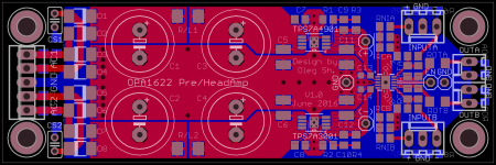
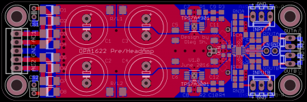
Slightly modified the design. Added output resistors pads... just in case")
I also have a question. I've made SMD pads for 10uF ceramic capacitors (C5, C6, C11, C12) recommended in the datasheet for the regs. I assumed 50V rating and X7R dielectric. Such capacitors usually come in 1210 package and are very thick. The question is, what is more important around the regs in my application, actual capacitor value or its size (parasitic inductance)? The regs are "Stable with Ceramic Capacitors ≥ 2.2 μF" as datasheet says, it also mentions X5R dielectric type as appropriate. What it does not specify is the actual capacitance which they need for stability. So, would it be OK to use 10uF 35V (or even 25V) X7R caps (they are available in smaller 1206 size) assuming that this board will not see more than 20 VDC at the regs input? The charts in the i-net show that X7R caps lose around half or even more of their capacitance if biased close to their rated voltage hence the question.
Regards,
Oleg
Attachments
Slightly modified the design. Added output resistors pads... just in case
I also have a question. I've made SMD pads for 10uF ceramic capacitors (C5, C6, C11, C12) recommended in the datasheet for the regs. I assumed 50V rating and X7R dielectric. Such capacitors usually come in 1210 package and are very thick. The question is, what is more important around the regs in my application, actual capacitor value or its size (parasitic inductance)? The regs are "Stable with Ceramic Capacitors ≥ 2.2 μF" as datasheet says, it also mentions X5R dielectric type as appropriate. What it does not specify is the actual capacitance which they need for stability. So, would it be OK to use 10uF 35V (or even 25V) X7R caps (they are available in smaller 1206 size) assuming that this board will not see more than 20 VDC at the regs input? The charts in the i-net show that X7R caps lose around half or even more of their capacitance if biased close to their rated voltage hence the question.
Regards,
Oleg
50% reduction in capacitance at rated voltage is the standard rule-of-thumb for power supply design. I would think that 10uF 35V X7R caps would be more than sufficient in the design. 25V seems too close to the proposed input voltage of 20V.
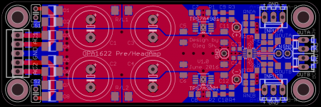
I've updated the design and I'm finally satisfied with the outcome. For a while I wasn't sure how to arrange the mute function without the use of external controller if the power goes down. I tried to route corresponding traces but I did not like the outcome. In the end I think it is best to implement the voltage divider between the V+, EN and GND pins on the underside of the PCB in such a way that it turns the OPA1622 ON/OFF if supply goes up/down.
Attachments
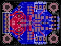
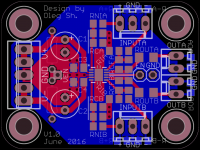
I have also made reduced version of the pre/head amp without the PSU part. This PCB is only 3x4 cm in size. I am going to order both designs with and without the PSU. Most probably I'll get a dozen of each design but I need only fraction of it. So I'm curious if there is interest in such PCBs from forum members?
Regards,
Oleg
Regards,
Oleg
Attachments
So I'm curious if there is interest in such PCBs from forum members?
I'm sure there would be if you can solder the IC to the board before shipping them.
Is pin 1 the pin closest to the * on the board?
I'm sure there would be if you can solder the IC to the board before shipping them.
It can be arranged but as Patrick pointed out
And then the customer receives the board, solders the rest himself, fires it up, and it does not work, or gets blown.
Who is to blame ? How to prove ?
and I am not ready to provide fully stuffed boards unless people are ready to pay and wait since it will not be fast and cheap.
Yes.Is pin 1 the pin closest to the * on the board?
Regards,
Oleg
Just for practicing found these. They have the same package as OPA1622 and cost 90 ct which is cheaper than frying OPA1622 while practicing. I probably need no more than two from my previous experience of "frying" the first two TPS7A... regs May be there are chipper options, but 2 Euros for the exercise compared to 7 Euros for OPA1622 is already big saving
May be there are chipper options, but 2 Euros for the exercise compared to 7 Euros for OPA1622 is already big savingAnd then the customer receives the board, solders the rest himself, fires it up, and it does not work, or gets blown.
Who is to blame ? How to prove ?
I didn't ask him to WARRANT anything. If someone isn't comfortable soldering the other components, then this may not be for them.
For no more cost than will probably be involved here, I would just throw it in the trash if it didn't work out. I wouldn't start pointing fingers or bad-mouthing OlegSh.
No big deal-it's just an IC.
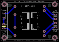
I am back with the question. I am currently looking for the transformer to use with the headamp. I;m aiming at 100mA max current draw from the regs which equals 50mA per channel max output. I guess it should be sufficient for my 32 Ohm headphones which I do not plan to run at ear splitting levels. So would it be fine to use a 3VA 2x6VAC block transformer in my case? It is good for up to 250mA current per secondary winding, is really small with the thickness of 17,6mm only and would fit in a small enclosure. Or it is better to overrate the transformer and go to the next size of 6VA? The problem I see is the enormous regulation of the smaller transformers of >50% at no load. This may create a lot of heat in the regs due to excessive voltage drop across them and the smaller transformer will run much hotter. Could someone comment what option is better?
The "enable" pin did not let me sleep well so I finally found a way to make the boards self-consistent. I introduced a voltage divider using two through hole resistors on the underside of the board. So now by selecting appropriate resistors and connecting VEN to EN by a wire jumper, the op-amp will turn ON(OFF) when the supply voltage goes up(down) above(below) given voltage threshold. Even with the VEN connected the output can still be muted by the external controller but one has to make sure that it can pull-down strong enough to override the VEN.
Also, to make sure that the "enable" jumper does not short VEN to V- under the op-amp I removed the solder pad under the chip. This makes it impossible to solder the thermal pad using regular soldering iron, but the hot air gun should have no problem with it.
so I finally found a way to make the boards self-consistent. I introduced a voltage divider using two through hole resistors on the underside of the board. So now by selecting appropriate resistors and connecting VEN to EN by a wire jumper, the op-amp will turn ON(OFF) when the supply voltage goes up(down) above(below) given voltage threshold. Even with the VEN connected the output can still be muted by the external controller but one has to make sure that it can pull-down strong enough to override the VEN. Also, to make sure that the "enable" jumper does not short VEN to V- under the op-amp I removed the solder pad under the chip. This makes it impossible to solder the thermal pad using regular soldering iron, but the hot air gun should have no problem with it.
Attachments
- Status
- This old topic is closed. If you want to reopen this topic, contact a moderator using the "Report Post" button.
- Home
- Amplifiers
- Headphone Systems
- Universal buffer/headamp based on OPA1622