"My" because I got the idea from my BCL clone and I've had great help from Abraxalito, thanks mate ")
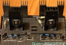
It's built and powered on with a temporary 7x12 dual rail supply.
I'll use LT1083's when I put it in it's case.
I was stomped by the DC offset I got, nothing close to LTSpice simulation indicated.
I replaced the opamp with another(same kind, OPA2134), and DC offset went from 1.4Vdc(declining slowly) to 0.05mV.
My question is if it's ok for the OPA2134 to get around 1.4Vdc on the inputs?
Without the DC-servo, I should've gotten around 65mV according to LTSpice simulation.
I used BD139/140-16, those have higher hfe from what I understand compared to the other versions.
Could that cause the offset? I did not match BJT's (BC547B, BC557B, bd139-16, bd140-16).
The 2SK170's in front of them are matched however.
Anyway, is the offset within margins for the OPA2134 or should I use another opamp?
Edit:
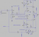
DC-servo circuit
It's built and powered on with a temporary 7x12 dual rail supply.
I'll use LT1083's when I put it in it's case.
I was stomped by the DC offset I got, nothing close to LTSpice simulation indicated.
I replaced the opamp with another(same kind, OPA2134), and DC offset went from 1.4Vdc(declining slowly) to 0.05mV.
My question is if it's ok for the OPA2134 to get around 1.4Vdc on the inputs?
Without the DC-servo, I should've gotten around 65mV according to LTSpice simulation.
I used BD139/140-16, those have higher hfe from what I understand compared to the other versions.
Could that cause the offset? I did not match BJT's (BC547B, BC557B, bd139-16, bd140-16).
The 2SK170's in front of them are matched however.
Anyway, is the offset within margins for the OPA2134 or should I use another opamp?
Edit:
DC-servo circuit
An externally hosted image should be here but it was not working when we last tested it.
Last edited:
For a few, happy, minutes I had -0.05mV to 0.05mV offset.
The day after when I planned on letting it run for a while.
I swapped the power supply for the intended on with two LT1083cp's.
I was back to 1.4Vdc offset.
Swapped back to the 7812/7912's and same there.
Built another jfet board using a 100% genuine matched quad of 2SK170GR's (all 3.7mA).
Same problem remained.
I'll take the DC-servo circuit offboard, leaving the dip8 socket and the power supply connection to it.
Build a DC-servo on a small PCB that I can plug into the dip8 socket.
This gives me the option to run the circuit completely free of the the DC-servo circuit, but also the optiion of trying different DC-servo circuits.
Hmm, either I've made some mistake or the design is not as good as LTSpice would suggest...
I get close to 2Vdc at power up with 33R load resistors to gnd but nothing on the inputs. For a brief moment of happiness yesterday I thought I had gotten it right...turns out the probe leads wasn't all the way inserted in the DMM
I've tried two versions of DC-Servo circuits and without DC-Servo, without and with DC-servo and a 6.8uF MKP on each output (seems to "saturate" after a while).
Next on the list of things to try is inserting filmcaps between jfet stage and diamondbuffer. Then maybe between BC547/557 and BD139/140.
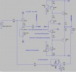
Versions I've tested soo far.
The one saying Vcc: +15Vdc and Vee: -15Vdc I tested with the same +/-12Vdc supply as the other. I also forgot to edit the dissipation for U1, that with 15V rails would be 117mW.
The heatsinks are overkill for this project, but I figured would minimize DC offset drift caused by heat.
The DIP8 socket is just placed in the pic while planning layout.
I get close to 2Vdc at power up with 33R load resistors to gnd but nothing on the inputs. For a brief moment of happiness yesterday I thought I had gotten it right...turns out the probe leads wasn't all the way inserted in the DMM
I've tried two versions of DC-Servo circuits and without DC-Servo, without and with DC-servo and a 6.8uF MKP on each output (seems to "saturate" after a while).
Next on the list of things to try is inserting filmcaps between jfet stage and diamondbuffer. Then maybe between BC547/557 and BD139/140.
Versions I've tested soo far.
The one saying Vcc: +15Vdc and Vee: -15Vdc I tested with the same +/-12Vdc supply as the other. I also forgot to edit the dissipation for U1, that with 15V rails would be 117mW.
The heatsinks are overkill for this project, but I figured would minimize DC offset drift caused by heat.
The DIP8 socket is just placed in the pic while planning layout.
Attachments
Your DC servo in post 1 has mixed up inverting and non inverting servos.
Peranders does a DC servo and will sell you a PCB if you can't do it yourself.
That would simplify things, will have a look at his site.
Though the design should not have that much offset to begin with, not according to LTSpice anyway?
I thought a DC servo should operate as follows.
At switch on the circuit without the DC servo should have very low offset.
As the DCservo powers on it starts to take over the offset control and then it monitors and adjusts it's output to maintain that low offset as the circuit warms up.
This is a bit different from what is usually done.
Builders set up their amplifier to have a low warm/hot offset and then couple the DC servo.
At switch on the DC servo is not yet fully operational and the cold amplifier has a big offset.
The servo does not control during those first few milliseconds, or maybe it takes a second to bring the offset under it's control.
Could a headphone survive during this switch on?
Could your ears survive.
Would a timer help by giving some time for the servo to take effective control before the output is connected to the load?
I thought a DC servo should operate as follows.
At switch on the circuit without the DC servo should have very low offset.
As the DCservo powers on it starts to take over the offset control and then it monitors and adjusts it's output to maintain that low offset as the circuit warms up.
This is a bit different from what is usually done.
Builders set up their amplifier to have a low warm/hot offset and then couple the DC servo.
At switch on the DC servo is not yet fully operational and the cold amplifier has a big offset.
The servo does not control during those first few milliseconds, or maybe it takes a second to bring the offset under it's control.
Could a headphone survive during this switch on?
Could your ears survive.
Would a timer help by giving some time for the servo to take effective control before the output is connected to the load?
I'm the first one to admit that I am a complete novice at designing circuits.
According to LTSpice, I should get about 65mV offset without the DC-servo connected.
In reality the offset is close to 2Vdc at start up, then slowly declining in to the mV range. This takes alot more time then a second though.
None of the BJT's are matched, the jfet's are closely matched though.
Putting film caps anywhere other than on the output severely fudged up transient and FFT.
So that goes out the window.
I've ordered a HP protection kit, I can't afford to replace my brand new Fidelio X2's.
Some sort of delay circuit would be an option, not shure where it would hook up or how it would look though.
I really appreciate the help btw
Got my old BCL clone fixed to have until I get the other projects done.
De-populated the PS part of the board, cut it off with my dremel.
I'll use a dual rail LT1083 supply for it.
Tested un-loaded today(with a temporary 7x12 supply), got 0.6mV both rails when cold.
I'll let it run for some time tomorrow and check for DC offset a few times.
De-populated the PS part of the board, cut it off with my dremel.
I'll use a dual rail LT1083 supply for it.
Tested un-loaded today(with a temporary 7x12 supply), got 0.6mV both rails when cold.
I'll let it run for some time tomorrow and check for DC offset a few times.
The easiest would be to trim your initial offset by using a 100R trimmer in either R9 or R12 position.
In your ltspice sims, you have a trimmer in the jfet buffer to compensate offset in the diamond buffer. Are they on your board, we can't see that part.
imho, I'd rather use the opamp to ditch the jfet input buffer and enclose the diamond buffer inside the opamp's feedback loop.
In your ltspice sims, you have a trimmer in the jfet buffer to compensate offset in the diamond buffer. Are they on your board, we can't see that part.
imho, I'd rather use the opamp to ditch the jfet input buffer and enclose the diamond buffer inside the opamp's feedback loop.
The easiest would be to trim your initial offset by using a 100R trimmer in either R9 or R12 position.
In your ltspice sims, you have a trimmer in the jfet buffer to compensate offset in the diamond buffer. Are they on your board, we can't see that part.
imho, I'd rather use the opamp to ditch the jfet input buffer and enclose the diamond buffer inside the opamp's feedback loop.
Hi,
I've thought about using trimpots for the CCS's.
Would be some re-working of the board as all but output resistors are 0805 SMD's.
I do have 50R 23-turn pots on the jfet board.
I've actually already made a schem for an opamp based board that will fit in the 12-pin header on the main board.
The last part of your post went straight över my head.
I have no idea on how to do that.
Tomorrow I'll hopefully get to test the headamp with the changes I made to the jfet board.
I had a discrete "opamp" (jfet's) in the BCL clone that inspired this build. I quite liked the sound compared to opamps.
That schematic wasn't really compatible with the "better" opamps though from my understanding.
Well, if you have a trimmer on the jfet board, let's start with that.
With the DC servo disconnected, what happens (meaning what is the output voltage) when you set the trimmer for 0V at the output of the jfet buffer ?
I'll hopefully get around to trying that today.
Thanks for helping it's appreciated
Should the input not be AC coupled, both in the sim and in real life ?
I'm sorry, I don't know what that means.
I'm sorry, I don't know what that means.
Your audio input (V3) is DC coupled to the amp input. In simulation your voltage source V3 has an effective DC resistance of zero ohms. This means that your servo can only develop a very small correction voltage at the amplifier input as you effectively have R13 and R2 in series to what is effectively 'ground'. The fix is to AC couple voltage source V3 via a suitable cap. R13 defines the input impedance of your circuit (so its low) and that means you need a relatively large cap to maintain LF response. You could make R13 much larger, say 1 meg. There is no noise penalty doing this.
In a real circuit, its a matter of chance what the DC output resistance of the source component is. It could be AC coupled, or it could be DC coupled direct to an opamp output.
So to remove this variability from your circuit you need to AC couple the input.
Did not get anywhere near 0Vdc on the jfet board outputs.Well, if you have a trimmer on the jfet board, let's start with that.
With the DC servo disconnected, what happens (meaning what is the output voltage) when you set the trimmer for 0V at the output of the jfet buffer ?
Got to 1.3Vdc & 1.5Vdc.
Then I noticed that the BC547B/BC547B's (not in CCS) got very hot. I could touch them and keep my finger on them for a few seconds but I was startled as they were more hot than I'd thought they'd be.
This was the longest I've had the headamp powered on, maybe 10-15min or so.
My fiance is not happy about me spending all day with the solder station, so I'll look into it some more tomorrow.
Probably need to put 100R trimpots in the CCS's as suggested(BJT CCS's).
I'll need to read this post a few times, preferably when I'm less tired.Your audio input (V3) is DC coupled to the amp input. In simulation your voltage source V3 has an effective DC resistance of zero ohms. This means that your servo can only develop a very small correction voltage at the amplifier input as you effectively have R13 and R2 in series to what is effectively 'ground'. The fix is to AC couple voltage source V3 via a suitable cap. R13 defines the input impedance of your circuit (so its low) and that means you need a relatively large cap to maintain LF response. You could make R13 much larger, say 1 meg. There is no noise penalty doing this.
In a real circuit, its a matter of chance what the DC output resistance of the source component is. It could be AC coupled, or it could be DC coupled direct to an opamp output.
So to remove this variability from your circuit you need to AC couple the input.
But I will read it again (and again) and compare it to my schematic as soon as I can manage to think again.
Experience has taught me that nothing good ever comes from pushing on when too tired.
Your audio input (V3) is DC coupled to the amp input. In simulation your voltage source V3 has an effective DC resistance of zero ohms. This means that your servo can only develop a very small correction voltage at the amplifier input as you effectively have R13 and R2 in series to what is effectively 'ground'. The fix is to AC couple voltage source V3 via a suitable cap. R13 defines the input impedance of your circuit (so its low) and that means you need a relatively large cap to maintain LF response. You could make R13 much larger, say 1 meg. There is no noise penalty doing this.
In a real circuit, its a matter of chance what the DC output resistance of the source component is. It could be AC coupled, or it could be DC coupled direct to an opamp output.
So to remove this variability from your circuit you need to AC couple the input.
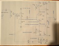
AC coupling:
Like this?
Attached build schematic.
Attachments
- Status
- This old topic is closed. If you want to reopen this topic, contact a moderator using the "Report Post" button.
- Home
- Amplifiers
- Headphone Systems
- "My" first design headamp, DC-servo question