Hi. This is my first post at this forum ")
This headamp is my summer project. I really want to build the amb M^3 headamp. However, I can't find the exact MOSFET in my city. So I replaced the output stage with the Sziklai pair, and I also replaced the jfet current source with bjt to minimize the cost.
I simulated this in ltspice and the THD at 1 kHz is 0.000003% (4v peak to peak, 32ohm load). However, I have some questions:
1. Does it work in reality?
2. How about the stability of the amp?
and I need your help in improving it!
Thanks!
Here is the ltspice file
https://drive.google.com/file/d/0Bw4wYHTYiD5sSDBIT3lCcmdiY1E/view?usp=sharing
This headamp is my summer project. I really want to build the amb M^3 headamp. However, I can't find the exact MOSFET in my city. So I replaced the output stage with the Sziklai pair, and I also replaced the jfet current source with bjt to minimize the cost.
I simulated this in ltspice and the THD at 1 kHz is 0.000003% (4v peak to peak, 32ohm load). However, I have some questions:
1. Does it work in reality?
2. How about the stability of the amp?
and I need your help in improving it!
Thanks!
An externally hosted image should be here but it was not working when we last tested it.
aaa by hoàngtuấnanh, trên FlickrHere is the ltspice file
https://drive.google.com/file/d/0Bw4wYHTYiD5sSDBIT3lCcmdiY1E/view?usp=sharing
An externally hosted image should be here but it was not working when we last tested it.
An externally hosted image should be here but it was not working when we last tested it.
Last edited:
Don't get me wrong, but OPA275 is not something from standard ltspice libraries. Would be better if you attached that one too.
Meanwhile a few questions. How much are you keen on OPA275? Sziklai pair? discrete output stage at all? There are several simplifications can be made, but really depends on what you have available and your selection of overall concept.
Meanwhile a few questions. How much are you keen on OPA275? Sziklai pair? discrete output stage at all? There are several simplifications can be made, but really depends on what you have available and your selection of overall concept.
You can replace the opa 275 with any audio opamp you have. The opa275 is the only working one in op amp libraries which I added. Probaly, there are errors in those libraries. I tried with the op27 in the original op amp library and it worked fine.
I used the normal bjt pair at first, then I saw the schematic of the cavalli kan kumisa 3 and copy the output stage. Due to this change, the THD decrease dramatically.
Another question, do we need such low THD? which value is good in practical?
I used the normal bjt pair at first, then I saw the schematic of the cavalli kan kumisa 3 and copy the output stage. Due to this change, the THD decrease dramatically.
Another question, do we need such low THD? which value is good in practical?
Hmmm.... it does not work exactly this way. While CFP (Sziklai) are really more linear than just a BJT, as you mentioned, when you go low enough in terms of distortion you will be highly likely limited by other factors. Like common mode distortions, opamp VAS linearity, input stage linearity at higher freq etc. So you can make a reasonable simplification in you output stage if its distortions will not dominate. In addition single BJT will be more predictable if your experience in the area is somewhat limited. I'm not saying that CFP as a bad choice, it just may not give you noticeable improvement.
Also I'm not a big fan of opa2134. Do you really need a JFET input?
Also I'm not a big fan of opa2134. Do you really need a JFET input?
Beside that, consider headphones you are going to use. A lot of headphones need barely a volt to achieve a desirable sound pressure level. If you focus on that you may get a better result with less efforts. Yes, it may not perfectly work with every possible pair of headphones, but does it really need to?
My headphone is grado sr225, 32 ohm impedance so I think it needs current more. NE5532, OPA2134 are quite cheap, i want to use them first then from what I feel I will change it to fit my taste. I'd like something bright and detailed, can you give me some suggestions.
This thing is getting more complicated. Before reading you replies I only considerd about the distortion, now I have more to learn. Althought I major in auditing I did several electrical projects. However none of them are about audio
I'm thinking of a more simple headamp. The output buffer is the buffer in the SOHA 2 with a opamp gain stage. Like this:
Ltspice file
https://drive.google.com/file/d/0Bw4wYHTYiD5saURjQU42ai1TUVU/view?usp=sharing
This thing is getting more complicated. Before reading you replies I only considerd about the distortion, now I have more to learn. Althought I major in auditing I did several electrical projects. However none of them are about audio
I'm thinking of a more simple headamp. The output buffer is the buffer in the SOHA 2 with a opamp gain stage. Like this:
An externally hosted image should be here but it was not working when we last tested it.
SE by hoàngtuấnanh, trên FlickrLtspice file
https://drive.google.com/file/d/0Bw4wYHTYiD5saURjQU42ai1TUVU/view?usp=sharing
needs more frequency correction:

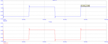
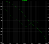
Adding 10pF between opamp's OUT and inverting IN does the trick. However be ready to fix stability on capacitive load (check device with 3m phones cable) - in microcap it oscillates with 300pF on output. Adding 2ohm resistor or damped inductance fixes that in simulator, but such things must be checked in reality cuz in my experience simulator often mistakes here. So just be ready for that (leave enough place on board for inductor )
Also if output shorted (that headphone jacks and cables do this sometimes) - then output transistors will be definitely killed with 6.7A current pulses. Adding 2Ohm resistor on output almost fixes this too.
Adding 10pF between opamp's OUT and inverting IN does the trick. However be ready to fix stability on capacitive load (check device with 3m phones cable) - in microcap it oscillates with 300pF on output. Adding 2ohm resistor or damped inductance fixes that in simulator, but such things must be checked in reality cuz in my experience simulator often mistakes here. So just be ready for that (leave enough place on board for inductor
)Also if output shorted (that headphone jacks and cables do this sometimes) - then output transistors will be definitely killed with 6.7A current pulses. Adding 2Ohm resistor on output almost fixes this too.
Attachments
Last edited:
They are like 98 dB/mW. You'll need ~10mW to get deaf. It is less than 20mA of current and 600mV of amplitude.My headphone is grado sr225, 32 ohm impedance so I think it needs current more.
In this case you don't need gain at all if you are using a PC soundcard or CD player as a source. They typically have 2Vrms @ 0dBfs at their output.
If it is so, you do not need more than +/-6V supply voltage and 15mA of a bias current for the output stage. If will significantly simplify your heatsinking task. Also remember about global warming and stuff
Before coming back to the schematic, did you consider using another opamp as an output stage? Looking at the power requirements I can say that even single LM6171(2) may be sufficient. As an advantage you will get current protection, small size etc.
Have a look at this. I had a bit of spare time ti fiddle with a few ICs - "The crocodile" headphone amp : headphones You can get a good result using a NE5534 and a single LM6172 per channel.
Last edited:
There is a simplified variant with NE5534 and couple of bjts. BD139/140 should work fine too.
Didn't optimize loop gain much since model is a bit off.
Keeping in mind NE5534 structure, output stage can be connected to pin 5 instead of pin 6, to make clipping more symmetrical.
Didn't optimize loop gain much since model is a bit off.
Keeping in mind NE5534 structure, output stage can be connected to pin 5 instead of pin 6, to make clipping more symmetrical.
Attachments
Last edited:
And it can still push out enough current then?Keeping in mind NE5534 structure, output stage can be connected to pin 5 instead of pin 6, to make clipping more symmetrical.
But speaking of pin 5, this seems an ideal place to apply some Class A bias from the positive rail. Not sure whether it's any better than pulling 6 towards the negative rail, but still. Or maybe do both at the same time, even? Has anyone tried that before?
I'm starting to like the good ol' 5534 more and more. Seems quite tweakable on both ends for sure. Maybe one of those days I'll end up designing an amp with them using bootstrapped supplies (or discrete bootstrapped cascode input stage), Class A bias and a discrete buffer, though I wouldn't be surprised in the least if it ends up being a stability nightmare...
And it can still push out enough current then?
Have look here. It will be connected to the same transistor but awoiding an extra diode junction and a resistor.
http://www.onsemi.com/pub_link/Collateral/NE5534-D.PDF
But speaking of pin 5, this seems an ideal place to apply some Class A bias from the positive rail.
In the example I've shown it will be in class A anyway. Extending thought a bit further, one of my friends uses a resistor connected between pin 5 and 6 to increase output stage bias current. Not sure if it really helps a lot. Depends on circumstances I guess.
Last edited:
- Status
- This old topic is closed. If you want to reopen this topic, contact a moderator using the "Report Post" button.
- Home
- Amplifiers
- Headphone Systems
- My first headamp project