What you guys think of this tone controll?.
3 Band Graphic Equalizer
I would use it between my source and the headphone amp.
Or should I use three band Baxandall eq described from Douglas self?
3 Band Graphic Equalizer
I would use it between my source and the headphone amp.
Or should I use three band Baxandall eq described from Douglas self?
Hi NPN.
This caught my eye and just a thought - have you seen the x-tone from Musicalfidelity? also an Op-Amp tone control. I personally like the way it uses stepped resistors rather than a pot. this is a pretty simple circuit but I'm not sure I would use the LF351 tho. Has the words low-cost in the datasheet")
Sure there are likely to be a lot of 'Objectors' to op-amps and even tone controls more generally but if it gets the job done for the listener I say 'why not'
Cheers
Andy
This caught my eye and just a thought - have you seen the x-tone from Musicalfidelity? also an Op-Amp tone control. I personally like the way it uses stepped resistors rather than a pot. this is a pretty simple circuit but I'm not sure I would use the LF351 tho. Has the words low-cost in the datasheet
Sure there are likely to be a lot of 'Objectors' to op-amps and even tone controls more generally but if it gets the job done for the listener I say 'why not'
Cheers
Andy
Something is missing from that circuit.
Maybe an output coupling cap?
I have a dumb question, how it is done for stereo (left and right), normally I don't need two knobs (bass, treble) per channel. Normally I have one treble and one bass knob for left and right.
But how wil it be done e.g. with Figure 13 of this Baxandall controll where I have to put the left and where the right signal?
But how wil it be done e.g. with Figure 13 of this Baxandall controll where I have to put the left and where the right signal?
How will it be done where I have to put the left and where the right signal?
There are indeed two pots, one per channel, but they are ganged together on a single shaft, and turn together.
This is typically done for tone, balance, and volume controls. Both channels are adjusted at the same time.
There often are tracking problems with this approach, with the channels differing in adjustment. Stereo Volume Controls
Sometimes there are two concentric knobs, and a special dual pot with concentric shafts, like on the Dyna PAT4.
Then the two channels can be adjusted separately, but with the panel space of one knob. Dynaco PAT-4 Preamplifier Component Info
Last edited:
Something is missing from that circuit.
Maybe an output coupling cap?
And a buffer to drive the tone control section.

I will use this schematic. Should I use it sfter the voltsge gain stage and buffer stage (headphone amp)?
One disadvantage is the phase inverting, but how will it affect on the music?
<< the phase inverting >>
Phase inversion will have no audible effect. The audio signal has already been flipped and re-flipped a dozen times or more on its way from the musician to the CD.
However, there might be other reasons to want everything in phase. In the case of a headphone amp it's usually no trouble to just make the output/driver op amp inverting.
Otherwise the only option is to add a buffer stage for the single purpose of inverting the audio signal. This is commonly done, it's done in all balanced line drivers.
<< Should I use it after the voltage gain stage and buffer stage >>
Without knowing all of your circuit, the sequence might be audio source ~> input buffer ~> tone controls ~> gain stage -> output stage.
In any case the tone control stage must be isolated from other stages or its varying impedances and phase shifts will do to the rest of the circuit what it does to the audio signal. This is why tone controls are located in-between op amps.
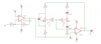
NOTE that the circuit shown in post #10 does not have an input capacitor. I simulated a 1uF input capacitor at the junction of R1 and R4, this worked well.
As others have pointed out, there must be an output capacitor (perhaps 220uF or 470uF) to protect the headphones from DC errors in the circuit.
.
Last edited:
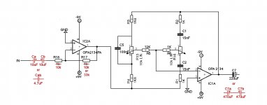
...What do you think of the new schematic?...Are the resistor values of the inverting buffer ok, or should they do it larger/smaller?
My opinion, assuming that the audio source is a CD player, computer, or similar:
There's no input capacitor before R18. Are you sure you don't need one? This would be a DC blocking capacitor (and also, working with R18, a high pass filter) that must be included unless you're certain the audio input will have no DC component. If you're not sure add about a 4.7uF capacitor to the input (for 10k Zin, as below).
As shown your input stage (an inverting buffer) presents a 1k input impedance (Zin), which is very low. It might be better to make R17 = R18 = 10k for a more reasonable 10k Zin.
The circuit as shown has no gain. You might not need any, but for a gain of 3.3 (not unexpected in a headphone amp) make R18 = 10k, R17 = 33k. The gain formula for inverting amps is Gain = Rf/Rg = R17/R18.
Making IC2a a gain stage instead of a buffer will have no effect on the shown circuit.
Not seen is the input capacitor for the feedback network mentioned in post #13. Without such a capacitor the simulation shows wonky response in the tone control circuit. Add a 1uF capacitor at the output pin 1 of IC2a.
It's not always easy to know which way electrolytic capacitors should point. If you have room it's effective to create a non-polarized electrolytic by hooking two in series, positive to positive, doubling their size. So the input capacitor would be two 10uF capacitors in series (for 10k Zin), the input capacitor for the tone controls would be two 2.2uF capacitors in series.
.
Last edited:
OK. Now if you are clever do it without the aurally debilitating effects of feedback. If you believe that you need equalization then you are looking to either take some artistic liberties with your program material (which is cool) - or you are trying to fix a sucky listening environment or transducers (should be solved by curing the illness and not trying to mask the symptom).
If your interest is in the former, that is you want to do Audio Art, then do what the Pros do, and use parametric equalization and reap serious control flexibility. Do that without feedback and you will have 'Eargasms'.
Lots of circuits are available for Parametric Equalizers.
As a quick reminder for those who though lack of use have forgotten what parametrics are, there are two general types, Shelving and Peak/Dip. Baxandall topology is a one-parameter equalizer of the shelving type.
Peak and Dip are just what that describes. Parameters to be adjusted are the "Q"or narrowness (sometimes thought of as the slope but that is not an accurate description) of the filter, the amplitude (how much boost or cut), and the center frequency.
Active filters tend to mess with soundscape as well both individual instrument timbre and ensemble layering. They generally suck for serious HI-Fi but are vital tools for sound re-reinforcement and commercial recording.
With R18=10k then i have a fg=33Hz its to high. I thought i don't need a input capacitor, because I have one after this tone control stage in my headphone amplifier!?My opinion, assuming that the audio source is a CD player, computer, or similar:
There's no input capacitor before R18. Are you sure you don't need one? This would be a DC blocking capacitor (and also, working with R18, a high pass filter) that must be included unless you're certain the audio input will have no DC component. If you're not sure add about a 4.7uF capacitor to the input (for 10k Zin, as below).
.
The problem is that then I get very loud johnson noise because the Zin is in the inverting circuit the feedback R.As shown your input stage (an inverting buffer) presents a 1k input impedance (Zin), which is very low. It might be better to make R17 = R18 = 10k for a more reasonable 10k Zin.
.
I had the problem with 10k and 15k Resistor in the feedback path in my non-inverting headphone amplifier with to much noise, then I reduced them to 680Ω and 1kΩ. The noise was disappear. But the zin was the same 47kΩ.
You mean C7?The circuit as shown has no gain. You might not need any, but for a gain of 3.3 (not unexpected in a headphone amp) make R18 = 10k, R17 = 33k. The gain formula for inverting amps is Gain = Rf/Rg = R17/R18.
Making IC2a a gain stage instead of a buffer will have no effect on the shown circuit.
Not seen is the input capacitor for the feedback network mentioned in post #13. Without such a capacitor the simulation shows wonky response in the tone control circuit. Add a 1uF capacitor at the output pin 1 of IC2a.
.
It's not always easy to know which way electrolytic capacitors should point. If you have room it's effective to create a non-polarized electrolytic by hooking two in series, positive to positive, doubling their size. So the input capacitor would be two 10uF capacitors in series (for 10k Zin), the input capacitor for the tone controls would be two 2.2uF capacitors in series.
.
Last edited:
I will use this schematic. Should I use it sfter the voltsge gain stage and buffer stage (headphone amp)?
One disadvantage is the phase inverting, but how will it affect on the music?
View attachment 477731
You can recover the initial signal polarity by adding an active Baxandall-Self volume control, using a 10 kOhm lin pot. It is an inverting circuit and offers a good level match between the stereo channels. I knew the circuit since years but built it only a few months ago. It gives me a nice feeling of comfort, I regret not to have tried it much sooner.
You can recover the initial signal polarity by adding an active Baxandall-Self volume control, using a 10 kOhm lin pot. It is an inverting circuit and offers a good level match between the stereo channels. I knew the circuit since years but built it only a few months ago. It gives me a nice feeling of comfort, I regret not to have tried it much sooner.
Yes it looks nice, but for my preamplifier its to much opamps, the power drain is to much for battery use. And before the volume control I need a further buffer stage for high Zin because the Zin in the Baxandall-self circuit is 1.27k at full gain.
Gesendet von iPad mit Tapatalk
.
It's all too easy to misplace a decimal when you don't solve formulas all day every day. Use a calculator: High Pass Filter Calculator
Please read this thread, emphasis on posts #6 and #7: http://www.diyaudio.com/forums/chip-amps/273566-input-damage.html
I doubt you'd get significant Johnson noise from one 33k resistor. I kinda-sorta suspect the hiss you're hearing might be caused by your power supply. Or do you have 0.1uF ceramic capacitors at the OPA2134 power pins 4 and 8 to ground?
(one capacitor from each pin to ground)
Apples and oranges. In the shown circuit Zin is set by R18. In a non-inverting circuit Zin is set by some unknown (to me) resistor connected to pin 3, not by the feedback network.
Volume control? What volume control? The circuit you posted shows no volume control. And for that matter it sounds like you have an additional buffer stage somewhere that's not shown?
I'm posting my suggestions below, but if you didn't post your complete circuit then discussion is meaningless. If you do post your complete circuit, please be sure to show the power supply, or post a link to the power supply circuit you're using.
.
It's all too easy to misplace a decimal when you don't solve formulas all day every day. Use a calculator: High Pass Filter Calculator
Please read this thread, emphasis on posts #6 and #7: http://www.diyaudio.com/forums/chip-amps/273566-input-damage.html
I doubt you'd get significant Johnson noise from one 33k resistor. I kinda-sorta suspect the hiss you're hearing might be caused by your power supply. Or do you have 0.1uF ceramic capacitors at the OPA2134 power pins 4 and 8 to ground?
(one capacitor from each pin to ground)
I had [a] problem with 10k and 15k Resistor in the feedback path in my non-inverting headphone amplifier with to much noise, then I reduced them to 680? and 1k?. The noise [disappeared]. But the zin was the same 47k?
Apples and oranges. In the shown circuit Zin is set by R18. In a non-inverting circuit Zin is set by some unknown (to me) resistor connected to pin 3, not by the feedback network.
...before the volume control I need a further buffer stage for high Zin because the Zin in the Baxandall-self circuit is 1.27k at full gain.
Volume control? What volume control? The circuit you posted shows no volume control. And for that matter it sounds like you have an additional buffer stage somewhere that's not shown?
I'm posting my suggestions below, but if you didn't post your complete circuit then discussion is meaningless. If you do post your complete circuit, please be sure to show the power supply, or post a link to the power supply circuit you're using.
.
Attachments
Last edited:
- Status
- This old topic is closed. If you want to reopen this topic, contact a moderator using the "Report Post" button.
- Home
- Amplifiers
- Headphone Systems
- Tone control