Hi. So I just got started in DIY audio and electronics and for my first project I decided to build a CMoy amplifier using tangesoft's instructions. I have been using this schematic and layout.
After successfully building one, I attempted to do another, and I've been having problems with it for days. I rebuilt the whole thing a couple of times now, changed practically all components, and I'm still getting a weird disbalance between the two channels, with the right one only getting about 1.5V and the left taking 6.5V from the 9V battery. After many tests checking the resistors, connections and caps, I noticed that the resistor R4 shows R=~0.9kohm although it is rated as 10kohm. Thinking I located the problem, I took it out and checked the voltage again, and it turned out to be good ~9.9 kohm. Obviously the resistance I was measuring on the board was the one coming from the parallel connection between R4 (10kohm) and R3 (1kohm). However, when I checked the R4 resistance on my functioning CMoy, R4 showed the expected R=10kohm.
At this point I don't really know what to do or how to further troubleshoot this. I am using a TL082 opamp with a single 9V battery. While I know that this is not an ideal setup, I am using it because I have confirmed that it works on the first one I built, and at this point I really just want to figure out what is wrong with this build.
Moved to H/phones ")
We have to start somewhere and so using the diagram in your link, can you measure and report the voltage on all the pins of the TLO82.
DO NOT have any headphones connected and measure from the virtual ground point.
Copy and paste this and add the voltages you get,
Pin 1 =
Pin 2 =
Pin 3 =
Pin 4 =
Pin 5 =
Pin 6 =
Pin 7 =
Pin 8 =
Moved to H/phones
We have to start somewhere and so using the diagram in your link, can you measure and report the voltage on all the pins of the TLO82.
DO NOT have any headphones connected and measure from the virtual ground point.
Copy and paste this and add the voltages you get,
Pin 1 =
Pin 2 =
Pin 3 =
Pin 4 =
Pin 5 =
Pin 6 =
Pin 7 =
Pin 8 =
Hey thanks for moving to the right sub.
Using this schematic
Pin 1 = 4.16V
Pin 2 = 0V
Pin 3 = 0.005V
Pin 4 = 0.058V
Pin 5 = 0V
Pin 6 = 0.002V
Pin 7 = 0.026V
Pin 8 = 4.16 V
A shorted connection on the output to ground would make R4 measure 0.9kohm or if low impedance headphones were still connected .
I have checked the R4 without the headphones connected and it shows the expected ~10kohm resistance, so I guess that explains the resistor value confusion.
Pin 4 is missing the negative supply. Pin 8 is correct at plus 4.16v.
Something basic is amiss there because pin 4 should go to the negative terminal of the battery although hard to say exactly what without first hand seeing it.
Do a double check now by measuring from the same virtual ground point but this time measure to first the positive and then the negative terminals of the battery. You should see a plus voltage for the first reading and a minus for the second with each being approximately one half of the total battery voltage.
No worries
OK, those voltages are spot on and so it looks as though the DC conditions are correct.
Even without test gear (such as a scope) we can still test all this but first I would look at your wiring, in particular the common grounds to the headphone and inputs. If you have a floating or missing ground to the headphones then you will get a weird echoey sort of sound.
Testing without a scope involves applying a known DC voltage direct to the input and checking that the output voltage is correct.
Not quite, I mean using known DC voltage. Your amp has a gain of 11 if you used the same values as on the diagram. So you need to rig up a low DC voltage to use as an input and one way to do that is to use just one added resistor.
(Those output voltages you measure are correct when no signal is applied)
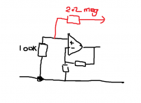
Look at the circuit and the 100k input resistor. If you connect a 2.2 meg resistor (shown in red) to the battery positive you will develop approx 0.18 volts on the amp input. Just ohms law. That should be amplified by the opamp to give around +2 volts at the output. If you then transfer the resistor to the battery negative terminal then the output should be - 2 volts.
The voltage you apply to the input has to be low enough to stand being amplified by 11 (the gain of the circuit) and come out at less than say 3.5 volts (to avoid clipping).
You use any method you like to derive the DC voltage, you could use a pot and a 1.5 volt battery to give a variable DC voltage.
(Those output voltages you measure are correct when no signal is applied)
Look at the circuit and the 100k input resistor. If you connect a 2.2 meg resistor (shown in red) to the battery positive you will develop approx 0.18 volts on the amp input. Just ohms law. That should be amplified by the opamp to give around +2 volts at the output. If you then transfer the resistor to the battery negative terminal then the output should be - 2 volts.
The voltage you apply to the input has to be low enough to stand being amplified by 11 (the gain of the circuit) and come out at less than say 3.5 volts (to avoid clipping).
You use any method you like to derive the DC voltage, you could use a pot and a 1.5 volt battery to give a variable DC voltage.
Attachments
So if I understand correctly, I should do something like this?
An externally hosted image should be here but it was not working when we last tested it.
The pot has to be across the battery but there is an even easier way to do this.
Look at the circuit. If you link out the 0.1uf coupling cap then you can connect a 1.5 volt battery directly across the normal audio input and use the existing volume control as the pot.
Use your meter to set the voltage on the opamp + input to any small value (say around 0.1 volts), do the maths (multiply by 11) and check the output is correct. So you would see 1.1 volts out for 0.1 in.
Then turn the battery around and make sure the output is negative 1.1 volts.
- Status
- This old topic is closed. If you want to reopen this topic, contact a moderator using the "Report Post" button.
- Home
- Amplifiers
- Headphone Systems
- Cmoy voltage fluctuation problem