I didn't expect this to be so fun!
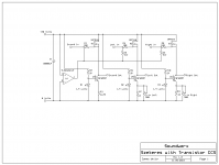
I came across this article about a really simple class A follower, by Greg Szekeres:
https://web.archive.org/web/2002061...com/projects/showproj.php?file=szeke1_prj.htm
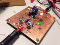
Having gotten some electronics experience lately (I took the contextualelectronics.com course about using KiCAD to design PCBs), I decided to whip one up, Manhattan style, just for kicks.
Surprisingly, it worked!
Before constructing, I did throw it into LTSpice just to be sure the mosfet and resistors wouldn't get too hot.
The FETs are just 2N7000's.
The input caps are Kemet 1uF film caps.
The output caps are 330uF OS-Cons (this was a guess, I had no idea if they sound any good, I just guessed they'd be better than stock electrolytics due to better ESR).
The regulator is a 7809, with a 100uF electrolytic on the input and on the output. I was tempted to go with a fancier output cap for the regulator, but if you go too low with the ESR I've read you can cause oscillation in these simple, old regulators.
First I tested with 100 ohm R4 (the FET bias resistors), but everything was barely warm to the touch so I stepped up to 47 ohms, and that seems fine.
Producing a working result on my first try is very encouraging, but there's a lot more I feel I need to learn. For example, I only know enough LTSPice to simulate current levels and heat levels. What do people use to simulate what the actual THD will be?
Also, I was surprised I couldn't find much material on single-ended class A FET headphone amps which use small FETs (e.g. TO-92 package). I'm sure there are FETs which sound better or worse than the 2N7000, but I had trouble finding info like that. Again, I'm assuming that if I had some sort of software which had the IV curves for these FETs, I could simulate and find the THD?
I came across this article about a really simple class A follower, by Greg Szekeres:
https://web.archive.org/web/2002061...com/projects/showproj.php?file=szeke1_prj.htm
Having gotten some electronics experience lately (I took the contextualelectronics.com course about using KiCAD to design PCBs), I decided to whip one up, Manhattan style, just for kicks.
Surprisingly, it worked!
Before constructing, I did throw it into LTSpice just to be sure the mosfet and resistors wouldn't get too hot.
The FETs are just 2N7000's.
The input caps are Kemet 1uF film caps.
The output caps are 330uF OS-Cons (this was a guess, I had no idea if they sound any good, I just guessed they'd be better than stock electrolytics due to better ESR).
The regulator is a 7809, with a 100uF electrolytic on the input and on the output. I was tempted to go with a fancier output cap for the regulator, but if you go too low with the ESR I've read you can cause oscillation in these simple, old regulators.
First I tested with 100 ohm R4 (the FET bias resistors), but everything was barely warm to the touch so I stepped up to 47 ohms, and that seems fine.
Producing a working result on my first try is very encouraging, but there's a lot more I feel I need to learn. For example, I only know enough LTSPice to simulate current levels and heat levels. What do people use to simulate what the actual THD will be?
Also, I was surprised I couldn't find much material on single-ended class A FET headphone amps which use small FETs (e.g. TO-92 package). I'm sure there are FETs which sound better or worse than the 2N7000, but I had trouble finding info like that. Again, I'm assuming that if I had some sort of software which had the IV curves for these FETs, I could simulate and find the THD?
Attachments
What do people use to simulate what the actual THD will be?
Run a .tran analysis and then view the FFT. You can find this in LTSpice by right-clicking on the graph window and then selecting View>FFT from the resulting menu. There are ways to automate this, so you might search Google.
Also, I was surprised I couldn't find much material on single-ended class A FET headphone amps which use small FETs (e.g. TO-92 package). I'm sure there are FETs which sound better or worse than the 2N7000, but I had trouble finding info like that.
I have no experience with the 2N7000. The 'Szekeres' circuit you built was intended to use IRF510 or IRF610, I believe. Some of the more "exotic" devices like 2SK213 might be better, but harder to find. Generally, you might look for parts which have low-ish input capacitance and high-ish transconductance. Might be interesting to try one of the newer SiC parts.
People usually aren't using TO-92 case FETs for Class A buffers because you need a fair bit of standing current for decent performance (typical values would be 30 to >100 mA), and cases like that have high thermal resistance, IOW they cannot dissipate that much. At modest Ic, consider replacing the drain resistor by a current source (e.g. LM317 based).
Distortion analysis is quite easy - add a spice line ".option plotwinsize=0" to turn off transient compression, add a voltage source at the input that you set up as a sine of desired amplitude and frequency, and run a transient analysis (about 10-20 sine periods, min timestep < {<1 period> / 2000}, use some slightly odd number like 2153 or so). Plot output voltage and run an FFT analysis (N = 32768 will do, Kaiser-Bessel window @beta = 20). Note that you do not need units - 1 kHz = 1k, 1 ms = 1m.
You can also have the required time periods computed automagically if you set a ".param freq=10k", enter sine frequency "{freq}" and replace 1 period by {1/freq}. (Note that the entire expression to be computed should be in curly brackets.)
People usually aren't using TO-92 case FETs for Class A buffers because you need a fair bit of standing current for decent performance (typical values would be 30 to >100 mA), and cases like that have high thermal resistance, IOW they cannot dissipate that much. At modest Ic, consider replacing the drain resistor by a current source (e.g. LM317 based).
Distortion analysis is quite easy - add a spice line ".option plotwinsize=0" to turn off transient compression, add a voltage source at the input that you set up as a sine of desired amplitude and frequency, and run a transient analysis (about 10-20 sine periods, min timestep < {<1 period> / 2000}, use some slightly odd number like 2153 or so). Plot output voltage and run an FFT analysis (N = 32768 will do, Kaiser-Bessel window @beta = 20). Note that you do not need units - 1 kHz = 1k, 1 ms = 1m.
You can also have the required time periods computed automagically if you set a ".param freq=10k", enter sine frequency "{freq}" and replace 1 period by {1/freq}. (Note that the entire expression to be computed should be in curly brackets.)
Thanks so much for the pointers!
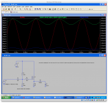
Here is where I'm at right now:


(note: the above screenshot is slightly old. It depicts a 650mW safe area and a 150 Ohm resistor / load line. That was updated to 400mW safe area and thus as 220 Ohm resistor / load line).


I was a bit surprised by the FFT shape. Is that normal?
Initially I started by simulating 21 cycles, and plotting cycle 10 through 20, and doing an FFT of that, which allowed the circuit 10 cycles to settle. I thought perhaps the output was being affected by capacitors slowly charging, so I upped that to 121 cycles, throwing the first 110 away, but it didn't seem to make any difference in the FFT shape.
- Status
- This old topic is closed. If you want to reopen this topic, contact a moderator using the "Report Post" button.
- Home
- Amplifiers
- Headphone Systems
- My first amp!