I want to build a simple relay for my headphone amp so i found the relay in the minimax is what i looking for but the QM12 need to be a darlington transistor, the alternative can be KSP13, KSP14, KSP25, KSP26, KSP27, MPSA13, MPSA27, MPSA28, MPSA29, 2N6426, 2N6427, 2N7052, 2N7053, BC372 or BC373 but i can't find any of those so can i substitute by darlington pairs consist BC550 and BD139 ?

Last edited:
No reason why not in principle.
I've no idea what the circuit is you are trying to describe, but just wondered if a FET would replace the darlington ? Something like a 2N7000
Sorry, i forgot to add the picture, you can see the schematic in my first post.
OK ")
Loads of possibilities... does it even need a darlington ? If RM2 is selected to provide sufficient base current then I would say no, and any small device could be used. The cap would have to be sized to suit so it gives the required delay.
Thoughts... the circuit isn't ideal as it stands. The voltage across CM3 only has to reach the vbe or (2*vbe for a darlington) and the thing conducts. You could drop a 2N7000 or any common N channel power FET in there and see advantages. RM2 could be high in value, up to 10meg if you wanted. That would allow a smaller cap (CM3) to be used. The big big advantage... the voltage across the cap would have to reach around 4 volts for the FET to conduct which is much better for accuracy. Improvements... whether a FET or ordinary transistor is used add a reverse biased diode across RM2. This will discharge the timing cap back into the supply on power off and ensure it is ready to work again immediately if needed.
Last edited:
OK
Loads of possibilities... does it even need a darlington ? If RM2 is selected to provide sufficient base current then I would say no, and any small device could be used. The cap would have to be sized to suit so it gives the required delay.
Thoughts... the circuit isn't ideal as it stands. The voltage across CM3 only has to reach the vbe or (2*vbe for a darlington) and the thing conducts. You could drop a 2N7000 or any common N channel power FET in there and see advantages. RM2 could be high in value, up to 10meg if you wanted. That would allow a smaller cap (CM3) to be used. The big big advantage... the voltage across the cap would have to reach around 4 volts for the FET to conduct which is much better for accuracy. Improvements... whether a FET or ordinary transistor is used add a reverse biased diode across RM2. This will discharge the timing cap back into the supply on power off and ensure it is ready to work again immediately if needed.
Thanks for your suggestion, i know little about electronic so i just want a simplest possible relay and i don't turn in on and off often so a pair of BC550 and BD139 will work, right? And if i'm right QM1, RM1, DM1, CM1 regulate the power supply (24V of the millet minimax) to 12V so they can use a 12V relay so can i obmit that section and just use a 24V relay?
Thanks for your suggestion, i know little about electronic so i just want a simplest possible relay and i don't turn in on and off often so a pair of BC550 and BD139 will work, right? And if i'm right QM1, RM1, DM1, CM1 regulate the power supply (24V of the millet minimax) to 12V so they can use a 12V relay so can i obmit that section and just use a 24V relay?
Yes and yes
A 24 volt relay is fine if that is what the supply is. Making a darlington from separate transistors is OK too. If you do all that, my one concern is that the design of the circuit relies on the voltage across the timing cap only reaching around 1.4 volts before the relay operates and that means you need a relatively long time constant of the timing components in order to use just a tiny part of that time constant.
That can be overcome by the addition of one zener diode.
Can you draw the schematic for me, thanks
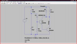
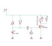
Here you go
Use your transistors. The value of C1 determines the delay. Zener diode D1 conducts only when a least 12 volts has been reached across the caps (actually 12 + vbe of the two transistors). R2 ensures no leakage of stray pickup will activate the relay. D2 can be any general pupose diode like a 1n4002 etc and its there to absorb the back emf from the relay coil.
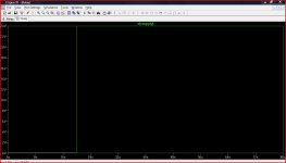
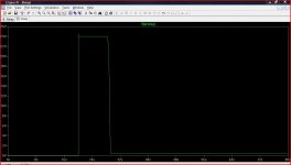
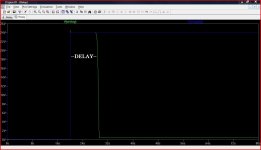
Try and understand how it works. This shows the supply going from zero to 24 volts at around 20 second in. The 24 volts is the moment you turn on the power. "Collector voltage" shows the voltage on the collector of the BD139. It goes to 24 volts at switch on (so relay dosn't operate) and then after a delay drops to zero as it turns on. The final picture shows the two traces combined so you can see the delay relative to the supply appearing.
Use your transistors. The value of C1 determines the delay. Zener diode D1 conducts only when a least 12 volts has been reached across the caps (actually 12 + vbe of the two transistors). R2 ensures no leakage of stray pickup will activate the relay. D2 can be any general pupose diode like a 1n4002 etc and its there to absorb the back emf from the relay coil.
Try and understand how it works. This shows the supply going from zero to 24 volts at around 20 second in. The 24 volts is the moment you turn on the power. "Collector voltage" shows the voltage on the collector of the BD139. It goes to 24 volts at switch on (so relay dosn't operate) and then after a delay drops to zero as it turns on. The final picture shows the two traces combined so you can see the delay relative to the supply appearing.
Attachments
Thanks for sharing it is helpful for me too
You are welcome
I have another more comprehensive design HERE that meets the requirements of repeatability and instant off and reset to ensure it works immediately its needed if the power is cycled quickly on/off/on etc
Here you go
Use your transistors. The value of C1 determines the delay. Zener diode D1 conducts only when a least 12 volts has been reached across the caps (actually 12 + vbe of the two transistors). R2 ensures no leakage of stray pickup will activate the relay. D2 can be any general pupose diode like a 1n4002 etc and its there to absorb the back emf from the relay coil.
Try and understand how it works. This shows the supply going from zero to 24 volts at around 20 second in. The 24 volts is the moment you turn on the power. "Collector voltage" shows the voltage on the collector of the BD139. It goes to 24 volts at switch on (so relay dosn't operate) and then after a delay drops to zero as it turns on. The final picture shows the two traces combined so you can see the delay relative to the supply appearing.
Hello Mooly,
A very nice circuit. I was planning to make a circuit for a HPA I am building inspired from DIYA SSII HPA. One thing I am a bit worried about is that supply is 15V, where as relay is 12V. would it be taken care of if i put a 3-5V zener in series with relay supply? Also is D2 necessary (may be discharge the cap)? I dont see it in your circuit.
could you help me point out any obvious mistakes ?
Attachments
Last edited:
D2 is good practice... not sure why I didn't include it in the sim tbh.
If you use a small power FET as you show then you can probably do away with the Zener D3 because the FET already needs around 4 volts or so before it will turn on. So just scale the cap and resistor to get the delay you want.
A small Zener is fine to go in series with the coil.
If you use a small power FET as you show then you can probably do away with the Zener D3 because the FET already needs around 4 volts or so before it will turn on. So just scale the cap and resistor to get the delay you want.
A small Zener is fine to go in series with the coil.
...supply is 15V, where as relay is 12V. would it be taken care of if i put a 3-5V zener in series with relay supply?...
Most "12V" relays will stand 15V for years. Most will pull-in at 70% and won't burn-up at 150% of nominal voltage. (But DO read the datasheet! Some relays are more fussy.)
A resistor is cheaper and kinder than a Zener. I don't know what a "351 relay" is. Assuming a "small" relay, perhaps 12V 40mA (300 Ohms), then 75 Ohms (50 or 100) 1/2 Watt in series will do.
Prasi,
I use a TO92 7812 regulator on my relay. Works well. This also give a consistent time delay on the RC.
If you recall, you did a circuit for me (a small headphone amp) years ago that has a very similar circuit - you could just copy that. It works well. It doesn’t have instant shut off to prevent turn off thump though.
To do that, a back to back double low RDson MOSFET and optoisolator driver and power management IC could be utilized for a headphone SSR. It would never wear out and never degrade the sound. You could then integrate a DC protection too.
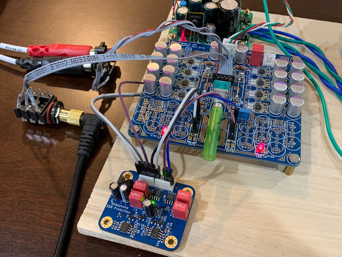
Here is one that Jhofland designed for me and used on my 8x parallel OPA1622 Headphone Amp.
I use a TO92 7812 regulator on my relay. Works well. This also give a consistent time delay on the RC.
If you recall, you did a circuit for me (a small headphone amp) years ago that has a very similar circuit - you could just copy that. It works well. It doesn’t have instant shut off to prevent turn off thump though.
To do that, a back to back double low RDson MOSFET and optoisolator driver and power management IC could be utilized for a headphone SSR. It would never wear out and never degrade the sound. You could then integrate a DC protection too.
Here is one that Jhofland designed for me and used on my 8x parallel OPA1622 Headphone Amp.
Last edited:
- Status
- This old topic is closed. If you want to reopen this topic, contact a moderator using the "Report Post" button.
- Home
- Amplifiers
- Headphone Systems
- Need help building a headphone relay