Thanks AGDR I received your package in the mail today and it is greatly appreciated. I've been using those same Energizer batteries since I first built the O2 a few years ago so it's probably time for some new batteries anyways. Let me know how much those Tenergy batteries cost and I'll paypal you the money.
OK, I'll take you up on that.
$9 and the postage is on me. They are from all-battery.com. The ones I'm sending are new and fresh off a charger.Even these 250mAhr are rated at only 200 full charge-discharge cycles from the datasheet:
http://www.all-battery.com/datasheet/10001_datasheet.pdf
After that the capacity drops and that voltage rebound effect when the load is cut off gets worse. Time for some new batts!
Money sent, thank you ADGR. It's to bad we can't use Li-ion 9v batteries in the O2 they have double the capacity of most NiMH 9v. I keep forgetting to ask you what kind of wire did you include with the pcb you sent? I really like that wire it's so easy to work with and very flexible! Is it silicone test lead wire?
. It's to bad we can't use Li-ion 9v batteries in the O2 they have double the capacity of most NiMH 9v. I keep forgetting to ask you what kind of wire did you include with the pcb you sent? I really like that wire it's so easy to work with and very flexible! Is it silicone test lead wire?It turns out that it was simply a bad soldering job on my part that was causing the small amount of dc offset on one channel. I reflowed all joints on the opamps and buffers and check out the readings now
An externally hosted image should be here but it was not working when we last tested it.
It turns out that it was simply a bad soldering job on my part that was causing the small amount of dc offset on one channel. I reflowed all joints on the opamps and buffers and check out the readings now
Hey that rocks!
Good find. I'll add reflowing the joints to the troubleshooting section I've added to the end of the build instructions.The wire is this stuff from eBay:
Super Flexible 24AWG Blue High Temp Silicone Wire RC Plane FPV Quadcopter 3' 6' | eBay
24 AWG, 40 strand with 200C insulation. Very flexible and the insulation won't shrink back when soldering.
I'll PM you the tracking # on the batteries.
I just got a new 49600. Just finished soldering it up. Can't fire up the O2 just yet. Left it at work. I'm going to give it a go with the OPA1641 to start with since they're already soldered on. I'm ok with a few mV of DC offset. What I'm looking for is more current output. I'm curious of the sound signature differences between the OPA140 vs. OPA827 vs. OPA1641.
I just got a new 49600. Just finished soldering it up. Can't fire up the O2 just yet. Left it at work. I'm going to give it a go with the OPA1641 to start with since they're already soldered on. I'm ok with a few mV of DC offset. What I'm looking for is more current output. I'm curious of the sound signature differences between the OPA140 vs. OPA827 vs. OPA1641.
Sounds good! I'll be interested to hear your listening impressions with the OPA1641.
So I have good news...
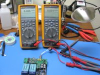
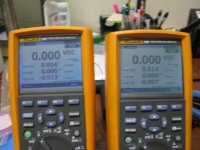
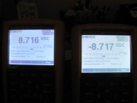
Finally got some time to put everything back in place and fired the puppy up. With the OPA1641 these are the measurements I got using a Fluke 289...
With the black probe on GND.
GND to Right .167mV DC
GND to Left -.170mV DC
I'd say these measurements are better than expected.
Sound wise, I'll be the first to admit my forte isn't in describing audio and its characteristics. I'll try though. My first impression is that there doesn't seem to be a huge difference in the overall sound between pre and post booster using the Alpha Dogs as my reference headphone. There seems to be a little more umph on transients, but not much. I didn't really write down what the pre booster O2 sounds like, so it might be my imagination. I'll have to really spend time with this opamp to get a feel, then make a switch to the OPA140. Since they're related or so I've heard, I wouldn't expect much of a difference at all. With the 827 it might be a whole different ball game.
Also, no issues with the relay thus far.
Overall, I'm glad I made the upgrade. The amp maintains the transparency the O2 intended in the first place.
With the black probe on GND.
GND to Right .167mV DC
GND to Left -.170mV DC
Not bad at all! That is still beating the O2's usual 1.5mV - 3.0mv by 10x - 20x. I just took another look at the OPA1641 data sheet. They show 1mV input offset as "typical" and 3.5mv as "maximum", but they don't show a minimum. Looks like that chip can beat the "typical" by quite a bit. That would make sense if it really is related to the OPA140. I think Sergey888 posted once that the two were related.
Thanks for the listening impressions! By the data sheet the OPA827 should have lower distortion and noise than the OPA140, at the cost of some slightly higher quiescent current (slightly reduced battery life). The DC offset with that chip starts at around 140uV then settles in at 30uV or so after a few minutes as it thermally stabilizes.
Last edited:
2.2uF timing cap - 1meg sense resistor - OPA827 - U4 pin 4 -dScoping the booster brd
I built up another O2 booster board today with OPA827 chips this time and wanted to post some new stuff.
I'm also going to let the cat out of the bag about something. John at JDS labs has agreed to dScope test the O2 booster board too, along with the ODA, and is in-process with that right now as time permits on his end. We will finally have some dScope measurements for the O2 booster board! A huge thanks goes out to John for the testing.
I've decided to adopt a change that John has suggested, reducing the O2 booster board relay turn-on delay from 5 seconds to 3. The relay timing capacitor C16 has been 10uF which produced 5 seconds. Going forward I'm modifying the BOM (and will repost today at the project's Google Drive link) to make C16 just another one of the 2.2uF MLCC capacitors that are also used for chip decoupling, which results in 3.1 seconds of delay. This removes one part type from the BOM, which is always a good thing.
I agree with John that 5 seconds was long enough to get a bit annoying if you turn your O2 on and off a lot. In the fast-peak detect photos below 3 seconds of turn-on delay still results in zero transients out the headphone jack going from O2 power off to O2 power on (and relay on), then zero transients going from O2 on to O2 off (and relay off). Down from the 200mV peak transient I measured for the stock O2, or the 800mV on/off transient that NwAvGuy measured in his writeup - and called OK.
In the photos I have DMMs connected to the batteries and set up for 15 minute recording. I've fully charged the batteries and will just let it run until cutoff. If all works out I should be able to post a full discharge curve, in 15 minute intervals, for the O2 + O2 booster board with OPA827's. This is playing music was some fairly sensitive test headphones the whole time, around 50mVrms into 32 ohms. I've changed the relay sense resistor in series with that R6 jack to 1meg ohm to see if that lowers the battery cutoff voltage.
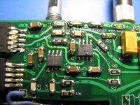
In the photos I posted a close-up of the OPA827 chips' orientation. With the OPA140s things are pretty easy because of the gold bar on the "pin 1" end. The OPA827's have a white dot near the "pin 1" end and the pin 1-4 side is beveled. Good luck seing that bevel though. I've tried. If you look at the chip right at the end with a strong light you can kinda see the bevel. It is better to go by the dot. Remember that the IC1 and IC3 op amps go in opposite directions! The dot on IC1 is towards IC2 (and marked on the silk screen). The dot on IC3 is toward the relay side of the board.
The photos also show how the JP5 hole is used. I ran a wire up from the bottom of the booster PC bosard, out the top of JP5, and tied it to pin 4 of the O2's U4 socket that is sticking up off the end of the booster board near JP5. This gives you a second connection to the O2's negative rail. The booster board already makes to connections to the O2's positive rail. Just lowers the connection impedance slightly.
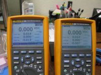
* The first photo shows the DC output offset with the OPA827 on first power-up of the new board running on batteries 26uV on one channel and 1uV on the other! These stayed stable over time. On AC with the full +/-12Vdc power rails the offset was about 20uV on each channel.
* The next photo shows the 2.2uF capacitor in the D16 position, along with a 1meg soldered in series with the JP6 wire. I'm done it exactly like Fsatsil did, which some heat shrink over the resistor end.
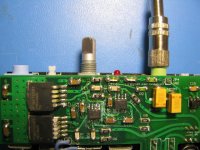
* Next shows the orientation of the OPA827 for IC1 with the while dot in the lower left corner of the chip in the photo. Unfortunately IC3 got drowned out in glare, but it goes the other way with the dot to the right.
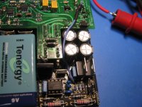
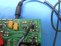
* Next is the connection from JP5 to the nearby connection pin sticking up past the edge of the board that goes to pin 4 of the O2's U4 holes. This makes a second power connection to the O2's negative rail for lowest connection impedance. The O2 mosfet right there is the fully insulated one in the O2's BOM. If you use a different mosfet with a metal back, and you make this connection to JP5, make sure the jumper wire doesn't short to the mosfet.
Also, in this photo, notice the O2 PCB resistor wedged in between that blue capacitor at the bottom of the photo and the O2's batteies. That is the O2 R25, the bottom of which is also OK as a connection point for that relay sense wire (in place of connecting it to the top of the O2's R8).
* The next photo shows proper spacing between the parts at the front of the booster board (like the LEDs) and the edge of the board. Make sure your LEDs don't hang over the edge. Also make sure none of the solder joints go all the way to the edge to prevent any chance of shorting against the front panel.
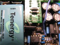
* The next photo shows that relay sense wire routed a little neater around the O2's filter capacitors on its way to the top of the O2's R8.
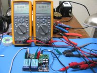
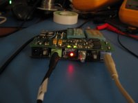
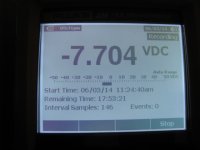
* The next three photos shows the fast-peak voltage readings on the headphone outputs. A pair of headphones is connected as load, otherwise just atmospheric noise would be picked up by high impedance meters during the open circuit when the relay cuts off. The first photo is O2 power off, the second is 4 seconds after power on (after the relay has turned on) , and the final is O2 power off. From the meters you can see there is just zero turn-on or turn-off transients - still - with the new reduced 3 second relay timing (down from the previous 5 seconds).
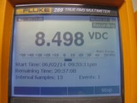
* The final photo shows the test setup to record the O2 battery voltages every 15 minutes until relay cutoff. At least that is the theory. If it works and I can graph it with the Fluke software I'll post the results.
I built up another O2 booster board today with OPA827 chips this time and wanted to post some new stuff.
I'm also going to let the cat out of the bag about something. John at JDS labs has agreed to dScope test the O2 booster board too, along with the ODA, and is in-process with that right now as time permits on his end. We will finally have some dScope measurements for the O2 booster board! A huge thanks goes out to John for the testing.
I've decided to adopt a change that John has suggested, reducing the O2 booster board relay turn-on delay from 5 seconds to 3. The relay timing capacitor C16 has been 10uF which produced 5 seconds. Going forward I'm modifying the BOM (and will repost today at the project's Google Drive link) to make C16 just another one of the 2.2uF MLCC capacitors that are also used for chip decoupling, which results in 3.1 seconds of delay. This removes one part type from the BOM, which is always a good thing.
I agree with John that 5 seconds was long enough to get a bit annoying if you turn your O2 on and off a lot. In the fast-peak detect photos below 3 seconds of turn-on delay still results in zero transients out the headphone jack going from O2 power off to O2 power on (and relay on), then zero transients going from O2 on to O2 off (and relay off). Down from the 200mV peak transient I measured for the stock O2, or the 800mV on/off transient that NwAvGuy measured in his writeup - and called OK.
In the photos I have DMMs connected to the batteries and set up for 15 minute recording. I've fully charged the batteries and will just let it run until cutoff. If all works out I should be able to post a full discharge curve, in 15 minute intervals, for the O2 + O2 booster board with OPA827's. This is playing music was some fairly sensitive test headphones the whole time, around 50mVrms into 32 ohms. I've changed the relay sense resistor in series with that R6 jack to 1meg ohm to see if that lowers the battery cutoff voltage.
In the photos I posted a close-up of the OPA827 chips' orientation. With the OPA140s things are pretty easy because of the gold bar on the "pin 1" end. The OPA827's have a white dot near the "pin 1" end and the pin 1-4 side is beveled. Good luck seing that bevel though. I've tried. If you look at the chip right at the end with a strong light you can kinda see the bevel. It is better to go by the dot. Remember that the IC1 and IC3 op amps go in opposite directions! The dot on IC1 is towards IC2 (and marked on the silk screen). The dot on IC3 is toward the relay side of the board.
The photos also show how the JP5 hole is used. I ran a wire up from the bottom of the booster PC bosard, out the top of JP5, and tied it to pin 4 of the O2's U4 socket that is sticking up off the end of the booster board near JP5. This gives you a second connection to the O2's negative rail. The booster board already makes to connections to the O2's positive rail. Just lowers the connection impedance slightly.
* The first photo shows the DC output offset with the OPA827 on first power-up of the new board running on batteries 26uV on one channel and 1uV on the other! These stayed stable over time. On AC with the full +/-12Vdc power rails the offset was about 20uV on each channel.
* The next photo shows the 2.2uF capacitor in the D16 position, along with a 1meg soldered in series with the JP6 wire. I'm done it exactly like Fsatsil did, which some heat shrink over the resistor end.
* Next shows the orientation of the OPA827 for IC1 with the while dot in the lower left corner of the chip in the photo. Unfortunately IC3 got drowned out in glare, but it goes the other way with the dot to the right.
* Next is the connection from JP5 to the nearby connection pin sticking up past the edge of the board that goes to pin 4 of the O2's U4 holes. This makes a second power connection to the O2's negative rail for lowest connection impedance. The O2 mosfet right there is the fully insulated one in the O2's BOM. If you use a different mosfet with a metal back, and you make this connection to JP5, make sure the jumper wire doesn't short to the mosfet.
Also, in this photo, notice the O2 PCB resistor wedged in between that blue capacitor at the bottom of the photo and the O2's batteies. That is the O2 R25, the bottom of which is also OK as a connection point for that relay sense wire (in place of connecting it to the top of the O2's R8).
* The next photo shows proper spacing between the parts at the front of the booster board (like the LEDs) and the edge of the board. Make sure your LEDs don't hang over the edge. Also make sure none of the solder joints go all the way to the edge to prevent any chance of shorting against the front panel.
* The next photo shows that relay sense wire routed a little neater around the O2's filter capacitors on its way to the top of the O2's R8.
* The next three photos shows the fast-peak voltage readings on the headphone outputs. A pair of headphones is connected as load, otherwise just atmospheric noise would be picked up by high impedance meters during the open circuit when the relay cuts off. The first photo is O2 power off, the second is 4 seconds after power on (after the relay has turned on) , and the final is O2 power off. From the meters you can see there is just zero turn-on or turn-off transients - still - with the new reduced 3 second relay timing (down from the previous 5 seconds).
* The final photo shows the test setup to record the O2 battery voltages every 15 minutes until relay cutoff. At least that is the theory.
If it works and I can graph it with the Fluke software I'll post the results.Attachments
-
 IMG_2725.JPG195 KB · Views: 134
 -
 IMG_2744.JPG194 KB · Views: 40
 -
 IMG_2742.JPG149.2 KB · Views: 37
 -
 IMG_2741.JPG145.3 KB · Views: 45
 -
 IMG_2740.JPG144.4 KB · Views: 51
 -
 IMG_2731.JPG197.9 KB · Views: 72
 -
 IMG_2730.JPG213.6 KB · Views: 60
 -
 IMG_2729.JPG178.5 KB · Views: 138
 -
 IMG_2728.JPG221 KB · Views: 135
 -
 IMG_2746.JPG143.5 KB · Views: 130
Last edited:
Cool stuff. Can't wait to see the dScope results.
How are you enjoying the OPA827 thus far? Do you have a preference towards the OPA140?
The two chips sound about the same to me. I haven't done a blind test though. I would expect the OPA827 to post some lower THD+N numbers based on the datasheets - it will be interesting to see what the test results say!
O2 + O2 Booster Board battery discharge curve
OK, it looks like the data logging for the battery voltage worked.
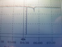
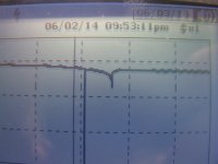
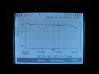
The first photo below shows the discharge curve, which is just about as typical as it gets for NiMH batteries. About 5 hours and 30 minutes all total. The big spike at 4hrs 30min is because I accidentally knocked the ground test lead off and didn't notice it for one 15 minute sample period.
The batteries start out at 9.6Vdc fresh off the charger. They are down to the nominal 8.4 volts after about 1hr 15 minutes, then stay relatively flat there for about 3 hours until about the 4 hour mark, when a slow dropoff starts.
That dropoff at the 5:15 mark to about 6.5Vdc tells the story. NiMH batteries stay relatively flat then suddenly just drop off the cliff like that when dead. Then it rebounds back to 8.2Vdc or so once the load is cut off. This is why the voltage has to be measured in that last 30 minutes or so before the O2's mosfets cut off. Measuring the battery voltage after cutoff will be rebounded back to a higher voltage.
This is why I have an O2 power management latch circuit board in the works to replace the O2's U2 chip. When that sudden battery dropoff happens the latch board will latch the O2's mosfets so they can't turn on again when the battery voltage rebounds. That prevents the "motorboating" sound some people get when their O2's cut off.
These voltage readings are with the OPA827 which pulls a couple of mA more than the OPA140. Using the OPA140 will give the best battery life. The greed LEDs also pull about 2.4mA with the 4.99K resistors in the BOM. You can increase those resistors to anything higher, like 10K, which will make the LEDs less bright but will save some battery power. Or remove the LEDs entirely - they are optional, but recommended for toubleshooting purposes. Even dim(er) they will tell you a lot about the O2's power rails.
I'm going to try the test again today with 5 minute samples rather than 15 minute to get some finer granularity on the curve.
OK, it looks like the data logging for the battery voltage worked.
The first photo below shows the discharge curve, which is just about as typical as it gets for NiMH batteries. About 5 hours and 30 minutes all total. The big spike at 4hrs 30min is because I accidentally knocked the ground test lead off and didn't notice it for one 15 minute sample period.
The batteries start out at 9.6Vdc fresh off the charger. They are down to the nominal 8.4 volts after about 1hr 15 minutes, then stay relatively flat there for about 3 hours until about the 4 hour mark, when a slow dropoff starts.
That dropoff at the 5:15 mark to about 6.5Vdc tells the story. NiMH batteries stay relatively flat then suddenly just drop off the cliff like that when dead. Then it rebounds back to 8.2Vdc or so once the load is cut off. This is why the voltage has to be measured in that last 30 minutes or so before the O2's mosfets cut off. Measuring the battery voltage after cutoff will be rebounded back to a higher voltage.
This is why I have an O2 power management latch circuit board in the works to replace the O2's U2 chip.
When that sudden battery dropoff happens the latch board will latch the O2's mosfets so they can't turn on again when the battery voltage rebounds. That prevents the "motorboating" sound some people get when their O2's cut off.These voltage readings are with the OPA827 which pulls a couple of mA more than the OPA140. Using the OPA140 will give the best battery life. The greed LEDs also pull about 2.4mA with the 4.99K resistors in the BOM. You can increase those resistors to anything higher, like 10K, which will make the LEDs less bright but will save some battery power. Or remove the LEDs entirely - they are optional, but recommended for toubleshooting purposes. Even dim(er) they will tell you a lot about the O2's power rails.
I'm going to try the test again today with 5 minute samples rather than 15 minute to get some finer granularity on the curve.
Attachments
Last edited:
I keep missing the 30 minute edit window on posts. Here is a test done by someone else on the Tenergy 250mAhr NiMH atteries:
Ben Krasnow: Testing Tenergy 9V NiMH batteries (discharge curve) (scroll down one page)
He measured 180 minutes = 3 hours with a 50mA load, vs. around 30mA with the OPA827, green LEDs, headphones, and 20mA of O2 headamp quiescent current for my 5.5hr measurment. His curve shows that same sudden dropoff to 6.5Vdc at the end.
Also note from this fellow's testing that the "250mAhr" battery actually is 200mAhr. That is quite common. I have another hobby with high power LED flashlights. The mAhr ratings of rechageable NiMH and lithium cells is a well known problem. I always reduce anything on the label by 75% - 80% right off the bat.
Here is a test done by someone else on the Tenergy 250mAhr NiMH atteries:Ben Krasnow: Testing Tenergy 9V NiMH batteries (discharge curve) (scroll down one page)
He measured 180 minutes = 3 hours with a 50mA load, vs. around 30mA with the OPA827, green LEDs, headphones, and 20mA of O2 headamp quiescent current for my 5.5hr measurment. His curve shows that same sudden dropoff to 6.5Vdc at the end.
Also note from this fellow's testing that the "250mAhr" battery actually is 200mAhr.
That is quite common. I have another hobby with high power LED flashlights. The mAhr ratings of rechageable NiMH and lithium cells is a well known problem. I always reduce anything on the label by 75% - 80% right off the bat.
Last edited:
Great test ADGR! My test wasn't nearly as scientific but It looks like you are getting about an hour longer battery life then I did. I got 4.5hrs using opa140s and an lme49720 in the gain stage. Did you use the stock njm2068 in the gain stage? What were the specs of the headphones you used? I don't know how much power the headphones I used were drawing but they are 32ohm 106db/1V which was the least sensitive pair I had and I set the volume to about the loudest I would ever listen. I'm going to try testing again to see if I can get a voltage measurement right before shutdown so I can find out exactly what the cutoff voltage is. I can't wait to see how the O2 w/booster measures!
My test wasn't nearly as scientific but It looks like you are getting about an hour longer battery life then I did. I got 4.5hrs using opa140s and an lme49720 in the gain stage. Did you use the stock njm2068 in the gain stage? What were the specs of the headphones you used? I don't know how much power the headphones I used were drawing but they are 32ohm 106db/1V which was the least sensitive pair I had and I set the volume to about the loudest I would ever listen. I'm going to try testing again to see if I can get a voltage measurement right before shutdown so I can find out exactly what the cutoff voltage is. I can't wait to see how the O2 w/booster measures!I'm not sure if I'm measuring it right but it looks like the headphones I used for the test were pulling significantly more current then the ones you used ADGR. I played some music at roughly the same volume as when I ran the test then measured the AC voltage and got peaks of around .25vac. .25v/32ohms=.0078a so nearly 8ma. Is this correct or am I doing it wrong?
I'm not sure if I'm measuring it right but it looks like the headphones I used for the test were pulling significantly more current then the ones you used ADGR. I played some music at roughly the same volume as when I ran the test then measured the AC voltage and got peaks of around .25vac. .25v/32ohms=.0078a so nearly 8ma. Is this correct or am I doing it wrong?
That is all correct. 0.25Vac(rms) = 250mV(rms) would be a lot more typical. The headphones I used in the test were pretty sensitive. My Shure cans need over a volt at normal listening levels. So your headphones pulling that 8mA would definitely run the batteries down faster.
I'm running another test right now with 2.5 second sampling instead of 15 seconds. I've also increased the (green) LED current limiting resistors R2 & R3 to 10K which will cut the LED current draw in half. I'm thinking that I may make that a permanent BOM change, leaving the 4.99K in as an alternate. The LEDs are still plenty bright at 10K being the right angle variety.
Last edited:
I ran another battery life test this time using a pair of very sensitive Sennheiser Ampheriors(18ohm 120db/1v) and the run time was right around 5hrs with a shut down voltage of 7.42v with a jp6 resistor of 100k. Do you think it's worth changing the JP6 resistor from 100k to 1meg?
I ran another battery life test this time using a pair of very sensitive Sennheiser Ampheriors(18ohm 120db/1v) and the run time was right around 5hrs with a shut down voltage of 7.42v with a jp6 resistor of 100k. Do you think it's worth changing the JP6 resistor from 100k to 1meg?
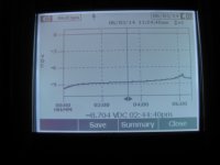
Probably not worth changing that JP6 series resistor. Below are the results of the second run I did yesterday with 2.5 minutes sampling. The result was also about 7.4Vdc cutoff with the 1 meg resistor. 7.4Vdc is OK. The various things I've read and some email exchanged with the manufacturer say the discharge should never go below 7.0Vdc to prevent damage to the battery. It looks like NwAvGuy has his set at somewhere around 6.5Vdc which was too low. Your batteries will last longer at the 7.4Vdc cutoff.
But it may be worth changing R2 & R3 to 10K from the 4.99K. The next to last photo below shows the brightness with 10K. That will reduce the battery current draw a little. This test run went for about 6 hours and 20 minutes. Some amount of that extra runtime was likely due to the smaller LED current. I also had different music playing which probably had an effect. Even the music involved can effect run time if the average level is higher and/or has more bass notes.
Photos below:
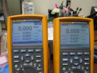
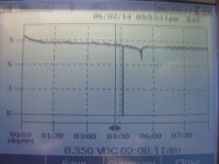
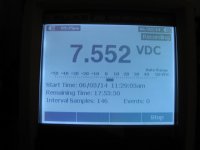
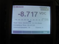
* The first two are 76 samples along, so 2.5min * 76 = 190 min = 3.2 hours. Stil 8.7Vdc! The discharge voltage is very symmetrical between the two batteries at this point.
* The next two are 146 samples along, which is 146 * 2.5 min = 365 min = 6.0 hours. As luck would have it the cutoff was just about 20 minutes after I took these pictures. I could easily tell when the cutoff occurred by when the two green LEDs went out.
* The next two are plots of the points for each battery. Notice how the battery voltage rebounds immediately after the load is cut off. That is what sometimes confuses the O2's power management circuit into thinking the batteries are charged up again and turning the O2 mosfets back on, resulting in a "motorboating" sound. If anyone gets that the best solution is to try fresh batteries, or try the O2 power management latch PC board I have in the works.
* The next photo shows the brightness level of the green LEDs with the 4.99K SMD resistors R2 and R3 replaced with 10K. Still plenty bright, IMHO.
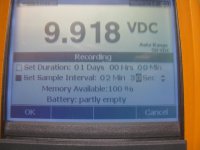
* The final photo shows the starting conditions with the batteries fully charged at 9.92Vdc.
Attachments
Last edited:
Thanks ADGR it looks like our results are very similar and the main reason for the battery life difference is the headphones used and music played. I will definitely change the led resistors to 10k for a little extra battery life Id also like to find an opamp for the gain stage with lower power consumption. The njm2068 is listed at 5-8ma and the Lme49720 I am using is listed at 10-12ma but neither datasheet says if that is per amplifier or per chip? Anyone know?
Id also like to find an opamp for the gain stage with lower power consumption. The njm2068 is listed at 5-8ma and the Lme49720 I am using is listed at 10-12ma but neither datasheet says if that is per amplifier or per chip? Anyone know?- Home
- Amplifiers
- Headphone Systems
- O2 headamp output booster PCB