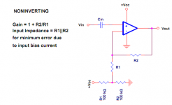
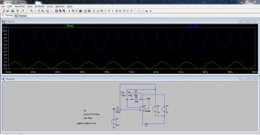
There are some other problems too. The midpoint voltage (junction of the 100K's) need to be at a low impedance to AC which means adding a cap across R2, in practice something like 10uf)
Why not set your simulation to have a mid point voltage created by using another voltage source rather than two resistors. That takes the time constant of the cap out of the simulation.
Why not set your simulation to have a mid point voltage created by using another voltage source rather than two resistors. That takes the time constant of the cap out of the simulation.

Remove the voltage divider network formed by the two 100K resistors (posters ORIGINAL circuit) from the bottom of R1 and relace with an earth . Place the 100K voltage divider network at the + input after Cin to set the midpoint and bias the + input then the notes still hold good .
")
i quit
capacitors........
Attachments
sharon1:
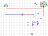
To see what is wrong with your original circuit, you must look at it first in strictly D.C. terms, and then again in strictly A.C. terms. To do that, simply remove all capacitors from the circuit, leaving their positions open (for the D.C. analysis), and determine whether the output would have a stable quiescent voltage (usually, but not necessarily, at the mid-supply voltage). Then, place shorting wires across the capacitor positions (for the A.C. analysis), and determine whether the applied A.C. signal would produce an output voltage swing within the amplitude limits of the op-amp, given the supply voltage and the D.C. quiescent point.
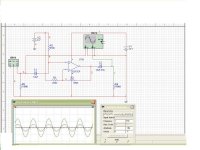
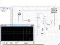
Post #14, by mjf, shows a circuit that will work. Among the things which will become evident, is that utilizing a bipolar power supply can remove the need for any of the coupling capacitors.
To see what is wrong with your original circuit, you must look at it first in strictly D.C. terms, and then again in strictly A.C. terms. To do that, simply remove all capacitors from the circuit, leaving their positions open (for the D.C. analysis), and determine whether the output would have a stable quiescent voltage (usually, but not necessarily, at the mid-supply voltage). Then, place shorting wires across the capacitor positions (for the A.C. analysis), and determine whether the applied A.C. signal would produce an output voltage swing within the amplitude limits of the op-amp, given the supply voltage and the D.C. quiescent point.
Post #14, by mjf, shows a circuit that will work. Among the things which will become evident, is that utilizing a bipolar power supply can remove the need for any of the coupling capacitors.
Last edited:
- Status
- This old topic is closed. If you want to reopen this topic, contact a moderator using the "Report Post" button.
- Home
- Amplifiers
- Headphone Systems
- whats worng with this circut