Turbon - will do! With those you could build 4 singles or take 2 of the boards and do the 2-board build option with just the power supply and ODAC in back in the longer B4-160 case and everything else on the front board..
I want to build one up that way myself (the two board option) in this next round. I'm adding "disconnects" on the power supply outputs to make it easy to wire. Essentially just a jumper on each supply rail. To use the board in single mode (one board for power supply and everything) you install the 2 jumpers. To use 2 boards the jumpers are left out and instead those holes are used to cable the V+ and V- rails from the power supply on the back board to the rest of the amp on the front board.
This time I'm going to order them with the ENIG (gold) finish which adds about $1 a board or so. I'm impressed with the pictures of the ENIG finish on opc's latest crop of "Wire' headamp boards.
Turbon - will do! With those you could build 4 singles or take 2 of the boards and do the 2-board build option with just the power supply and ODAC in back in the longer B4-160 case and everything else on the front board..
I want to build one up that way myself (the two board option) in this next round. I'm adding "disconnects" on the power supply outputs to make it easy to wire. Essentially just a jumper on each supply rail. To use the board in single mode (one board for power supply and everything) you install the 2 jumpers. To use 2 boards the jumpers are left out and instead those holes are used to cable the V+ and V- rails from the power supply on the back board to the rest of the amp on the front board.
This time I'm going to order them with the ENIG (gold) finish which adds about $1 a board or so. I'm impressed with the pictures of the ENIG finish on opc's latest crop of "Wire' headamp boards.
I haven't digged into this into depth but can one run 1 channel on one board? Then it would take 3 boards for a complete system
 and maybe give an extra bit of separation and punch. Just earth the input of the channel not wanted on the two amp boards. You better double your order to the pcb maker . If possible I will need 6 boards... 1*3 + 1*2 + 1. Hehe
Regards
I haven't digged into this into depth but can one run 1 channel on one board? Then it would take 3 boards for a complete system
Interesting idea! You could do that in two different ways. One way is just fully build up two ODA boards, power supplies and everything on both boards, then feed them with two transformers. That would give you a full dual-mono setup. Then do exactly what you say and ground the input on the unused channel on each board. So lets say you have boards "A" and "B", both fully built up with all the parts:
* On "A" ground the left channel input and feed one of your source channels into the right channel on that board. The grounded channel only pulls a small amount of idle current from the power supply, the other "working" channel up to the 320mA.
* On "B" same as "A", but with the other source channel fed to the right channel.
One hiccup though comes in what to do about a case and board mounting. I'll have to ponder that a bit. The boards are intended for edge slot mounting in those box enclosures cases. I don't think I put any mounting holes in the PCBs. Then there is the issue of headsinking the voltage regulators to something instead of the back panel, if not up against a back panel.
I'll check into something. ProtoPanel, the folks who I had mill the panels, have added a line of cases similar to the Box Enclosure stuff, but as I recall they were a lot taller and/or wider.
Another problem would be the on/off switch, to make sure both boards came on and off at the same time. I'll ponder that one too. If you were putting the boards in a larger case it would probably be possible to mount an external on/off and external input / output jacks on the case and then just cablet things over to the boards.
The other way to do this is use a common power supply on one of the boards. So fully populate all the parts on board "A", but on board "B" leave off the power supply parts and just cable the power over from the power supply on board A to board B. So the power supply winds up shared but the amp sections are separate. This arrangement works because the grounded channel on each board only pulls the small amount of idle current, making the net current draw on the power supply just slightly larger than on one board with both channels active. But again finding a case the works could be a challenge!
I'm probably going to order 40 ODA boards in this next run, so I'll be keeping a bunch on hand this time.
Last edited:
Amazing work! I was thinking about giving this build a try, but had a couple questions:
- is the polarity for C51 in the gerber files under ODA 8_11_2013 still backward? I was thinking about ordering a handful of boards (that ENIG finish DOES look tempting..) and will just tweak the "+" to a "-" if so.
- will a standard Yoyodyne ODAC board really fit along with this in a B4-080? Any idea whether the USB-in on the ODAC board can be made directly accessible from a back panel, or would I have to run a wire out? It seems like a pretty tight fit on paper..
Amazing work! I was thinking about giving this build a try, but had a couple questions:
Thanks!
C51 is still backwards on the board text. I've been meaning to fix that. I'll make that change and re-post the Gerbers, probably by mid-week this coming week. I've noticed a couple of part labels for parts on the top wound up on the bottom. I'll fix that too. I know Turbon has been interested in some boards too so I should get a revision done.
I would agree with you on the ENIG finish. For the $16 or so they charge it would be worth it.
The ODAC fit hasn't been tested, at least that I'm aware. I don't have an ODAC. I've have just been going by the dimensions.
But I do know for certain that the ODAC will fit underneath the O2 PC board in the standard B2-080 case, with insulating tape wrapped around it. I've seen several posts over the last year or so from people who have done that here and on Head-Fi. The Box Enclosures mechanical dimensions show 5.70mm from the bottom of that O2 board to the bottom of the case. And keep in mind this is with parts leads sticking down through the bottom of the O2 PCB, further reducing available space, yet the ODAC still fits.
For the B4-080 case for the ODA here thier mechanical dimensions show 5.75mm from the top of a PC board in the top slot to the top of the case. So with the ODA you would actually have 0.05mm more space that what is under the O2 PC board, with no part leads sticking down (or up). So I would say there is an excellent chance it would fit. Just slide a blank PC board in that top slot of the B4-080 with the ODAC mounted to it, or as with the O2 just wrap tape around the ODAC and let it sit loose. For the blank PC board you could just cut a piece of blank perfboard or copper clad board to size, or simply use a second unpopulated ODA board.
I've just double-checked on ODAs I have here and there are no clearance problems in getting a board in the B4-080 top slot. The tallest things are two of the filter capacitors and I sized those to just barely clear. A top-slot board slides right in.
As for for USB hole in the back (or front) panel, some DIY work would be required there.
Without having an ODAC here I don't have enough mechanical information to give dimensions for the USB holes, or for mounting the ODAC to that top board. It may very well be necessary to use a USB cable to go from the panel to the ODAC board, although I see nothing that would prevent having the ODAC flush with the back panel. The B4-080 case does not have an extrusion protruding from the top, down the middle, like it does on the bottom (for a center screw). So everything is free and clear on the top.
Last edited:
dace - some additional thoughts - I also have a new version of the ODA in the works that adds DC output offset nulling. Gets rid of the typical O2 3mV or so output offset. When I posted back to Turbon above that is what I had in mind in suggesting he wait a bit. I have layout done, but I need to go back and clean it up. I'm going to post a revision of the current one next week regardless. But if you would want to wait another couple of months I'll probably have the next version available. The time delay is to finish the layout, fab it, mail it, load it, and testing.
Some other changes with the next version-
* The voltage select switch in the back goes away. That feature turned out to be not as useful as I expected. The amp's DC output offset changes just slightly in the different voltage settings, like 200uV or so, so running at one voltage makes the new DC offset null circuit more effective. Also allows a bit more spacing between the voltage regulators. Right now the mica insulators have very little clearance between them side-to-side. It all fits fine, but with more spacing it would require a little less alignment effort for the micas.
* The relay has its own voltage regulator. Prevents having to run board traces from the pre-regulators back to the relay circuit.
* Power jack sticks through the rear panel. To make it look a little more professional I'm going to try having the face of the power jack flush with the front surface of the rear panel, which means a square cutout in the rear panel. I avoided that until now to use a more DIY-friendly drill hole, like the O2 does, but it seems most folks bought a pre-drilled panel anyway.
* Holes for the inductors are removed. In the posts above I discovered the inductor I had specified didn't work out since it wasn't shielded (or toroid) so those PC holes have to be jumpered across, still leaving a C-R-C input filter. Eliminating those inductor pads entirely leaves more spacing room for the power parts. That reminds me, on the revision next week I'll show silk screen for a wire jumper across those inductor holes.
When I send the boards for this new version out I will do it with ENIG.
Last edited:
Thanks for the replies! And for double-checking the top clearance in a B4. Just running a USB cable through the back panel with a rubber grommet might not be so bad anyway. Or I might try to get creative and make an acrylic enclosure that would fit it more easily if I can figure out how to use some channel-style heatsinks to replace the TO-220 kit you have specified since there'd be no metal back panel to dissipate heat - I think Aavid makes some that might work. That would look great with a black PCB which I think Seeed Studio makes now. Maybe I'll hold off until you have the next major revision though.
The changes all sound good. a 3mV output offset already seems great, but lower is certainly objectively better and I suppose that's the point! I immediately thought "why not add a pot or DC servo" but of course went back and found you already thought of that, and its downsides Would you just keep the +/-16V rails then? Or even 18V, since at first glance it looks like the current BOM would mostly support it?
I also agree it's often easier/nicer to just get pre-drilled panels instead of going the DIY route for most people now that so many places online will do inexpensive one-offs. Any chance you'll have Front Panel Express .fpd files as well for the next round, since you mentioned those at one point?
The changes all sound good. a 3mV output offset already seems great, but lower is certainly objectively better and I suppose that's the point! I immediately thought "why not add a pot or DC servo" but of course went back and found you already thought of that, and its downsides
Would you just keep the +/-16V rails then? Or even 18V, since at first glance it looks like the current BOM would mostly support it?I also agree it's often easier/nicer to just get pre-drilled panels instead of going the DIY route for most people now that so many places online will do inexpensive one-offs. Any chance you'll have Front Panel Express .fpd files as well for the next round, since you mentioned those at one point?
Or I might try to get creative and make an acrylic enclosure that would fit it more easily if I can figure out how to use some channel-style heatsinks to replace the TO-220 kit you have specified since there'd be no metal back panel to dissipate heat - I think Aavid makes some that might work.
One fellow PM'ed me a few months ago about 3D printing a case of the ODA, which sounded great until I remembered that issue of the back panel, at the least, needing to be metal for heat sinking. So by all means, if you can figure out a way around that, an acrylic enclosure would look cool.
No RF shielding with the plastic, unless someone knows a way to get it carbon-loaded, but for most environments it probably won't matter.I immediately thought "why not add a pot or DC servo" but of course went back and found you already thought of that, and its downsides
There is a tricky entry in the absolute maximum values table in the NJM4556A datasheet. Maximum input voltage is 15V for supply voltages above 15Vdc.
I originally had +/-17Vdc rails until I spotted that. The LME49600 chip only swings to within 2 volts or so of the rails, so with +/-16Vdc rails that max swing into the NJM4556's would be 14Vdc. I wanted at least a volt of buffer space there since that 15 is in the "absolute max" chart.I'm not a fan of DC servos due to settling time, subsonic oscillation potential, and some feedback leakage of the actual signal back into the gain stage along with the correction DC level. Plus the DC (zero) level of real music is always moving around slightly with time. What I want to correct is just the fixed offset of the chips and not the combined zero level of the music + chip offset level that the integrator would extract. Going to a higher order filter + integrator helps nuke any signal being fed back, and would produce a longer time constant for averaging, but then it would have 2nd or 3rd order feedback response that can lead to subsonic (1-10 Hz) oscillations. Unless the poles are properly matched with zeros, which would force me to dust off my control systems textbook and Laplace transform math from 30 years ago, lol.
So I decided that just feeding in a DC level with a pot is the simplest, especially when I tested a bunch of NJM4556ALs and found the DC offset was very consistantly a +1.5Vdc or so. Never negative. I think DC servos are best used for instrumentation where what is being correctly is slight shifts in DC values over months or years as components age.
Any chance you'll have Front Panel Express .fpd files as well for the next round, since you mentioned those at one point?
Make that a definite. I was intending to do that with the current version and never did. Proto Panel has done great work but I know FPE is the 800lb gorilla in the room and some folks may prefer to use them.
Last edited:
No RF shielding with the plastic, unless someone knows a way to get it carbon-loaded, but for most environments it probably won't matter.
There are a few places online where you can get tin-doped indium oxide coated glass or plastics for $20ish/sqft or less that are transparent in the visible spectrum but good for shielding (with the added bonus that they often become opaque under a UV light and look neat). There are some aerosol carbon paints too but they tend to block some visible light.
Maximum input voltage is 15V for supply voltages above 15Vdc.
Hm, good catch - though did you mean below 15V? Looking at the datasheet:
"For supply voltage less than ±15V,the absolute maximum input voltage is equal to the supply voltage"
Edit: oops nevermind, I see.
Last edited:
Hm, good catch - though did you mean below 15V? Looking at the datasheet:
"For supply voltage less than ±15V,the absolute maximum input voltage is equal to the supply voltage"
Yeah their wording is a bit of a logic puzzle.
I take that to mean if the supply rail is less than +/-15Vdc, like +/-12Vdc, then the maximum input match the rail voltage, +/-12Vdc here. But I take it to mean for supply voltages above +/-15Vdc (the chip is rated up to +/-18Vdc max) the maximum input would be +/-15Vdc regardless, since they have already indicated the two levels track if less than +/-15Vdc and they seem to be flagging an exception of some kind at the +/-15Vdc level. Hey very interesting about the metal-doped transparent plastics being available! I didn't know that. Problem solved. It would look great and still have good RF sheilding.
One last question: it doesn't look like your current layout has any drill holes for standoffs - any thought to adding some in the next version to provide for more flexible mounting options?
I like it! Some holes would allow the board to be mounted in a bigger box. In fact, I'll see if I can find space on the current version too when I re-spin that this week.
ODA V2.0 - my version of a O2 Desktop Headphone Amplifier
Here in a update on this project. I didn't meet my estimate a couple of posts above of having a revision out in a week. I've been working on it the last few days. I was further along on V2.0 with the DC offset null/adjust and some other stuff than I remembered. I'm going to go ahead and send V2.0 out to fabrication in a couple of weeks and see if that offset null circuit works.
Several changes in V2.0, below...
* I've used dace's suggestion above and put M2 holes on each corner of the board so it could be stand-alone mounted in a larger case. M2 (threaded) sized metal or nylon standoffs in all sorts of lengths are readily available on eBay and probably Mouser and Digikey.
* The two CLC inductors that had to be jumpered are gone, replaced with another series 0.5R resistor under the board for the resulting CRC AC powerline noise filter.
* The DC power jack is now moved 2mm forward to be flush with the front surface of the back panel. This results in the plastic jack insulation all the way around between the hole and metal back panel, a good thing. This means a rectangular hole in the back panel. I'll post a new
Proto Panel rear panel CAD file. As per dace's suggestion above I'll also post those CADs in Front Panel Express format.
* The relay circuit has its own voltage regulator, a high voltage LM317HV unit, which reduces the length of traces needed to feed it.
* The output of the AC CLC section of the power supply now feeds the pre-regulator chips via a short length of shielded mini-coax cable (grounded at just one end of course). This keeps the output of the CLC filter, which still has a couple of volts of DC sawtooth on it, away from the "clean" power traces coming out of the final regulators and feeding the board. No concerns here on the previous version, it is silent and noiseless, I'm just prepping for the day when I can measure this thing all the way down to -140dB noise floor with an AP or possibly this QA400 thing with the notch filter board I have out to fab.
* Disconnects added to the power supply section. The JP18 and JP19 V- and V+ test points (output of the power supply section) are now split into two sets of isolated holes which are not connected by default and require a jumper be soldered into both to connect the power supply output to the rest of the board. This does a few things. It allows the power supply to be tested independantly from the rest of the board. If you get a short in the rest of the board in the future (like my C51 screw-up on the previous board) you can just remove the jumpers to test if your power supply section is still OK. Also in the case of using the 2-board build option with the power supply on the rear board in the longer B4-160 case, the disconnects make it easy to run power from the power output half of JP18 and JP19 on the rear board to the power input half of JP18 and JP19 on the front board. The existing boards had the power supply section hard-wired via traces into the rest of the board, making it harder (would have to cut the two power supply PCB traces) to troubleshoot a short on the board.
* The DC output offset circuit is added to both channels. Essentially a filtered zener voltage reference (running in zener breakdown below 6.1V and not the noiser avalance breakdown above 6.1V) divided down to just a few milivolts, then feeding a 20 turn 10 ohm trimmer to null out the normal 3mV or so amplifier output offset voltage. A safety resistor is added so if the trimmer pot wiper dies years down the road the output won't go up to some DC voltage. The filter corner frequency is set so the AC (music) signal looking back into the circuit isn't affected in any way. Should be possible to get the DC offset down to 200uV
* The voltage select switch is gone. This feature turned out to be less useful that I originally planned. Plus with the new DC offset null circuit there is a slight 200uV change going between the two voltages. Running at just +/-16Vdc solves that problem. Eliminating the switch allows slightly more spacing between teh 4 voltageds regulators, making the positioning of the insulating micas a little less critical. Yet another reason the back panel is changing. The front panel is still the same in V2.0 as the previous version.
* The volume pot is now independently star grounded, something I wanted to do in the original version. Lol - again just getting it -140dB noise floor testing ready.
* Several text label screw-ups that folks building the previous version let me know about, like missing pin 1 dots on IC1 and IC2, the IC5 label on the wrong side of the board, etc. The outlines for the 4.7uF caps were slightly wrong even though enough space was left. That is fixed now. I had over-shrunk the holes for the power jack and switch pins in the previous version, which is fixed now. OK to drill those out slightly with a micro-sized drill and Dremel in the previous boards if necessary, there are no middle-board traces in those areas.
* The DC offset null circuit required one of the 6 4.7uF coupling caps be re-tracked for the offset null circuit, so the coupling caps are now down to 5 in parallel. This changes the corner frequency from 1.2Hz to 4 or so, but still much lower than the O2.
* and, of course, my C51 polarity screw-up is fixed.
I'm going to have the next batched fabbed with ENIG (gold) surface finish.
Here in a update on this project. I didn't meet my estimate a couple of posts above of having a revision out in a week.
I've been working on it the last few days. I was further along on V2.0 with the DC offset null/adjust and some other stuff than I remembered. I'm going to go ahead and send V2.0 out to fabrication in a couple of weeks and see if that offset null circuit works. Several changes in V2.0, below...
* I've used dace's suggestion above and put M2 holes on each corner of the board so it could be stand-alone mounted in a larger case. M2 (threaded) sized metal or nylon standoffs in all sorts of lengths are readily available on eBay and probably Mouser and Digikey.
* The two CLC inductors that had to be jumpered are gone, replaced with another series 0.5R resistor under the board for the resulting CRC AC powerline noise filter.
* The DC power jack is now moved 2mm forward to be flush with the front surface of the back panel. This results in the plastic jack insulation all the way around between the hole and metal back panel, a good thing. This means a rectangular hole in the back panel. I'll post a new
Proto Panel rear panel CAD file. As per dace's suggestion above I'll also post those CADs in Front Panel Express format.
* The relay circuit has its own voltage regulator, a high voltage LM317HV unit, which reduces the length of traces needed to feed it.
* The output of the AC CLC section of the power supply now feeds the pre-regulator chips via a short length of shielded mini-coax cable (grounded at just one end of course). This keeps the output of the CLC filter, which still has a couple of volts of DC sawtooth on it, away from the "clean" power traces coming out of the final regulators and feeding the board. No concerns here on the previous version, it is silent and noiseless, I'm just prepping for the day when I can measure this thing all the way down to -140dB noise floor with an AP or possibly this QA400 thing with the notch filter board I have out to fab.
* Disconnects added to the power supply section. The JP18 and JP19 V- and V+ test points (output of the power supply section) are now split into two sets of isolated holes which are not connected by default and require a jumper be soldered into both to connect the power supply output to the rest of the board. This does a few things. It allows the power supply to be tested independantly from the rest of the board. If you get a short in the rest of the board in the future (like my C51 screw-up on the previous board) you can just remove the jumpers to test if your power supply section is still OK. Also in the case of using the 2-board build option with the power supply on the rear board in the longer B4-160 case, the disconnects make it easy to run power from the power output half of JP18 and JP19 on the rear board to the power input half of JP18 and JP19 on the front board. The existing boards had the power supply section hard-wired via traces into the rest of the board, making it harder (would have to cut the two power supply PCB traces) to troubleshoot a short on the board.
* The DC output offset circuit is added to both channels. Essentially a filtered zener voltage reference (running in zener breakdown below 6.1V and not the noiser avalance breakdown above 6.1V) divided down to just a few milivolts, then feeding a 20 turn 10 ohm trimmer to null out the normal 3mV or so amplifier output offset voltage. A safety resistor is added so if the trimmer pot wiper dies years down the road the output won't go up to some DC voltage. The filter corner frequency is set so the AC (music) signal looking back into the circuit isn't affected in any way. Should be possible to get the DC offset down to 200uV
* The voltage select switch is gone. This feature turned out to be less useful that I originally planned. Plus with the new DC offset null circuit there is a slight 200uV change going between the two voltages. Running at just +/-16Vdc solves that problem. Eliminating the switch allows slightly more spacing between teh 4 voltageds regulators, making the positioning of the insulating micas a little less critical. Yet another reason the back panel is changing. The front panel is still the same in V2.0 as the previous version.
* The volume pot is now independently star grounded, something I wanted to do in the original version. Lol - again just getting it -140dB noise floor testing ready.
* Several text label screw-ups that folks building the previous version let me know about, like missing pin 1 dots on IC1 and IC2, the IC5 label on the wrong side of the board, etc. The outlines for the 4.7uF caps were slightly wrong even though enough space was left. That is fixed now. I had over-shrunk the holes for the power jack and switch pins in the previous version, which is fixed now. OK to drill those out slightly with a micro-sized drill and Dremel in the previous boards if necessary, there are no middle-board traces in those areas.
* The DC offset null circuit required one of the 6 4.7uF coupling caps be re-tracked for the offset null circuit, so the coupling caps are now down to 5 in parallel. This changes the corner frequency from 1.2Hz to 4 or so, but still much lower than the O2.
* and, of course, my C51 polarity screw-up is fixed.
I'm going to have the next batched fabbed with ENIG (gold) surface finish.
Attachments
Last edited:
Now it's really getting serious.
Stellar work, agdr, hope I'll be able to join in at some point.
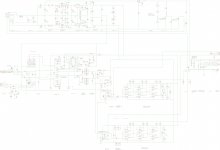
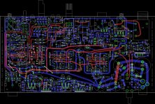
In the meantime, does this forum support uploading vector graphics?
If it does, you might consider exporting those Eagle drawings as PDF. (Print -> Print As File (PDF)). Done properly the size should be comparable to a 600dpi PNG file.
Stellar work, agdr, hope I'll be able to join in at some point.
In the meantime, does this forum support uploading vector graphics?
If it does, you might consider exporting those Eagle drawings as PDF. (Print -> Print As File (PDF)). Done properly the size should be comparable to a 600dpi PNG file.
Count me in, 3 boards
Regards
Will do! I just started a list. The project google drive link is now at:
https://drive.google.com/folderview?id=0B67cJELZW-i8VmhVNk5PODNtZnc&usp=sharing
Then "80x160 PCB" folder -> "3_1_2014 V2.0" folder. The list of folks interested will be "orders" file. Again, all at cost, which looks like it would be around $15 a board plus shipping. I've found Seeed Studio's standard shipping gets to me in around 10 days, with tracking all the way. I can apply the $$ saved over DHL express to the ENIG gold plating and wind up with the boards still at $15.
Now it's really getting serious.
Stellar work, agdr, hope I'll be able to join in at some point.
In the meantime, does this forum support uploading vector graphics?
If it does, you might consider exporting those Eagle drawings as PDF. (Print -> Print As File (PDF)). Done properly the size should be comparable to a 600dpi PNG file.
Thanks!
I've converted the PNGs that Eagle generated into PDFs, but they actually double in size. I have those PDFs posted now, along with the original PNGs, at that project Google Drive link above. For good detail when zooming in I've been dumping the layout at 800dpi and the schematic at 200dpi, hence the big files. What I really should do is also export at half that dpi for the forum posts, just to keep the size down for limited bandwidth internet connections, then put the full blown thing at the Google link.Parametric bass boost top-slot board
Here is some other news about the project. The PCB holes for the two (optional) attenuation resistors, R29 and R30, also essentially work as disconnects between the output of the gain stage and the input of the volume pot. Something else can take the signal at this point, mess with it, then send it back to the pot.
The something else I have in mind is a parametric bass boost (state variable filter) board that would fit upside down in the top slot. Power and ground on the top board would be fed from the extra holes on the power supply disconnects (that is why the extra holes, to power other stuff in the case). The board would work with any of the past ODA versions too.
Any more I'm coming to the opinion that ruler flat frequency response (which the ODA does) is less important than the whole thing simply sounding the best. A lot of headphones - and probably some ears - seem to have varying levels of bass roll-off that really needs to be corrected. A parametric bass booster would allow the break point to be varied between 30Hz and 400Hz or so, then the gain amount of boost varied independently, all with front panel pots. The optional bass boost circuit on the ODA board right now is fixed is corner frequency and gain once the parts are soldered on, which would make it hard to adjust on the fly for different headphones.
A board in the top slot would also give more front panel space, above the ODA board, for the 4 pots required. Frequency and gain for both channels.
I haven't designed anything here yet, just a thought at this point, but I'm going to keep it in mind for a future project.
Equalizer software for a digital player can do the same thing of course, but I kind of like having physical pots to turn for this kind of thing.
Last edited:
Here is an update on this ODA V2.0 project.
The PC board went out to fabrication yesterday and will have the ENIG (gold) finish. Usually takes them about a week to fabricate, then another 7-10 days to go from China to the US. Then a few days for me to build one up and test it. If all tests out OK then I will post the PC board Gerber files at the Google Drive link.
I've done a renumber on the board part numbers to make the layout look as snappy as possible. I'm in the process of updating the BOM to match the new part numbers and I'll post that, along with the latest layout and circuit, over the next day or two at the Google Drive link.
I'm going to do the same thing I did with the O2 booster board pins and offer anything that has to come from Digikey (Mouser doesn't stock or out of stock) at-cost to ship with the board. That way at least only one order to Mouser will be neeeded. I'll also pack lengths of the mini-coax cable that the power supply uses now along with the boards.
Last edited:
- Home
- Amplifiers
- Headphone Systems
- A version of an O2 Desktop Amp (ODA)