Well, it started with this : http://www.diyaudio.com/forums/headphone-systems/221439-midgard-low-distortion-lateral-fet-output-headphone-amplifier.html
However, things turned out in such a way that I did have neither time nor money to pursue it further.
A few days ago I decided to take a look at it again and there has been some rather major changes.
List of changes :
Dual matched NPN monolithic SSM2212 transistors for the input pairs.
Dual matched PNP monolithic SSM2220 transistors for the current mirrors.
BC850C are used in the LED based current sources.
BC860C for the VAS.
Semelab ALF08NP16V5 dual N+P channel Lateral FET is used for the output transistor.
LTP bias current is 2.6mA through each of the input transistors, VAS bias current is 5.2mA, output stage bias current is 115mA.
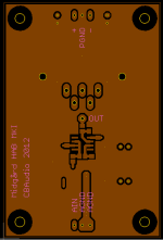
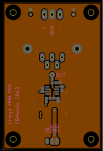
Almost everything is SMD so the board is a lot smaller this time. Old board were 100mm X 100mm for 1 channel, the new board is 90mm X 50mm, which is 45% of the previous size and it might end up even smaller. Something like 70-80mm X 50mm should be a possibility.
Smallest components are the SOT23 BC850C/BC860C transistors, resistors and capacitors are 0805 and up.
The input RC filter will be using either a C0G/NP0 ceramic capacitor or a PPS film capacitor. The same goes for the Cdom capacitor, that is also either C0G/NP0 or PPS film. I have not decided yet.
100nF bypass capacitors will either be some kind of film capacitors or X7R ceramic capacitors.
I know a lot of people do not like ceramic capacitors for audio use but X7R are great for supply bypassing and NP0/C0G are just as good as some of the best film/silver mica capacitors when it comes to low distortion. On top of that they are extremely stabile over temperature and are free from the usual piezo electric effect seen in X5R/X7R and lower quality ceramic capacitors.
However, things turned out in such a way that I did have neither time nor money to pursue it further.
A few days ago I decided to take a look at it again and there has been some rather major changes.
List of changes :
Dual matched NPN monolithic SSM2212 transistors for the input pairs.
Dual matched PNP monolithic SSM2220 transistors for the current mirrors.
BC850C are used in the LED based current sources.
BC860C for the VAS.
Semelab ALF08NP16V5 dual N+P channel Lateral FET is used for the output transistor.
LTP bias current is 2.6mA through each of the input transistors, VAS bias current is 5.2mA, output stage bias current is 115mA.
Almost everything is SMD so the board is a lot smaller this time. Old board were 100mm X 100mm for 1 channel, the new board is 90mm X 50mm, which is 45% of the previous size and it might end up even smaller. Something like 70-80mm X 50mm should be a possibility.
Smallest components are the SOT23 BC850C/BC860C transistors, resistors and capacitors are 0805 and up.
The input RC filter will be using either a C0G/NP0 ceramic capacitor or a PPS film capacitor. The same goes for the Cdom capacitor, that is also either C0G/NP0 or PPS film. I have not decided yet.
100nF bypass capacitors will either be some kind of film capacitors or X7R ceramic capacitors.
I know a lot of people do not like ceramic capacitors for audio use but X7R are great for supply bypassing and NP0/C0G are just as good as some of the best film/silver mica capacitors when it comes to low distortion. On top of that they are extremely stabile over temperature and are free from the usual piezo electric effect seen in X5R/X7R and lower quality ceramic capacitors.
Attachments
Last edited:
Put me down for 4 PCBs.
Well, I might need some time to get done with the layout as well as actually building a pair of boards.
")
I should have a pair of boards up and running sometime at the end of January if all goes well and I can find the time for it.
It is a hobby after all.
you might look at some of the interesting dual transistors mentioned in the SW-OPA thread, lower noise and distortion again, as well as physically smaller than the SSM duals.
what size CDOM are you looking at? the AVX Accu-P thin film caps, but only available up to 12pf for the 50v parts, and 22pf I think for te 25v parts. these are more stable and linear again than C0G at very high frequency. there are some new thin filmVishay parts up to 10pf in 25v also.
the transistors I speak of are ones like
NXP BCM61B (2xNPN) and BCM62B (2xPNP)
NXP BCV61 and BCV62 (dual NPN and PNP current mirrors)
MMDT4401/4403 (dual NPN+NPN, PNP+PNP) (all specifically made for use as current mirrors) or MMDT4413 (complementary)
even new dual N-Channel Jfets in SMD in the form of MCH5908. some R-Ohm duals etc etc. lots of great little parts if you dont mind SMD, apparently a boom of AM radio in China is driving some new parts useful for us.
Last edited:
you might look at some of the interesting dual transistors mentioned in the SW-OPA thread, lower noise and distortion again, as well as physically smaller than the SSM duals.
what size CDOM are you looking at? the AVX Accu-P thin film caps, but only available up to 12pf for the 50v parts, and 22pf I think for te 25v parts. these are more stable and linear again than C0G at very high frequency. there are some new thin filmVishay parts up to 10pf in 25v also.
the transistors I speak of are ones like
NXP BCM61B (2xNPN) and BCM62B (2xPNP)
NXP BCV61 and BCV62 (dual NPN and PNP current mirrors)
MMDT4401/4403 (dual NPN+NPN, PNP+PNP) (all specifically made for use as current mirrors) or MMDT4413 (complementary)
even new dual N-Channel Jfets in SMD in the form of MCH5908. some R-Ohm duals etc etc. lots of great little parts if you dont mind SMD, apparently a boom of AM radio in China is driving some new parts useful for us.
Thanks, have not seen those currents mirrors before.
I think I will keep using SSM2212 for the input pair, but some of those dual PNP current mirrors are quite interesting.
EDIT : I think I will use NXP BCM62B for my current mirror, high gain, low noise and as a bonus, small size.
Last edited:
cool, actually my bracketed comments didnt work out correctly, I was referring to everything before I said 'all specifically designed as current mirrors' when I said that, not just that line. the BCM and BCV are the best parts of the lot too IMO, great choice! some of the builders may not thank me haha, but hey if the results are good its all good right?
thats what Scott Wurcer specifies in his SW-OPA (the BCV62A) so thats a pretty strong recommendation if ever ive seen one!
thats what Scott Wurcer specifies in his SW-OPA (the BCV62A) so thats a pretty strong recommendation if ever ive seen one!
what would be cool, since youve got a bit of space up the top of the board, would be if you put a hole in the PCB to allow alternate mounting of the mosfet under the board, then you could make a cute, but good and masculine chassis design with 2 x conrad or similar heatsinks like MF15-75/MF15-100 as the walls with the amps screwed to them and the PSU in the center. or of course the floor of a case if it was chunky enough
another interesting set of parts you may not have seen
another interesting set of parts you may not have seen
Last edited:
what would be cool, since youve got a bit of space up the top of the board, would be if you put a hole in the PCB to allow alternate mounting of the mosfet under the board, then you could make a cute, but good and masculine chassis design with 2 x conrad or similar heatsinks like MF15-75/MF15-100 as the walls with the amps screwed to them and the PSU in the center. or of course the floor of a case if it was chunky enough
Interesting idea, I thought about something similar, like using the board as a small pure Class A amp, putting out 8 Watt into 8 ohm.
However, for the moment I am too keen on adding that option to the board.
Those are really interesting, single chip matched input pair+current mirror, that is something special.
Those are really interesting, single chip matched input pair+current mirror, that is something special.
Hmm, maximum Vds for all of them is 10.6V so a cascode is needed across the input pair. But still interesting.
However, using a dual matched N-channel FET with a cascode as the input pair and then a dual matched P-channel FET as a current mirror should work well.
Been looking at the datasheet of BCV62 and BCM62B more closely and I am not too happy about what I see.
The current matching is not nearly as accurate compared to what the SSM2220 delivers.
They have higher gain than the SSM2220 and they are cheaper than the SSM2220 but as always you do not get anything for free.
I will probably stay with the SSM2220 as current mirror. They cost a great deal more and have less gain but current matching is just a lot better.
Last edited:
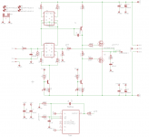
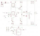
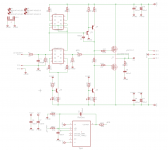
I am very close to the final layout.
There has been a few changes compared to what presented in my first post.
I added another transistor to the VAS and it is now a beta enhanced VAS, this reduced THD1 to around 0.0001xx% at close to full power. THD20 is a respectable 0.001xxx% at close to full power. Going from 32 to 250 to 600 Ohm loads, the THD1 and THD20 does not change significantly.
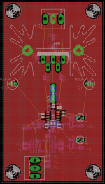
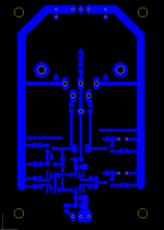
Final board size will be 50mm x 80mm so it is quite compact.
The end result is a high quality Class A headphone amplifier than can drive almost anything on the market, from 32 to 600 Ohm and with very low distortion
I am more than satisfied.
This is the design that I have felt the most excited for out of those I have designed and built so far.
I am also working on a high quality supply board for it. Current plan is a cap multiplier to lower ripple as well as getting rid of as much mains nosie as I can and then followed by a Sulzer regulator for truly low ripple and noise. Sulzer regulator alone show 50Hz and 100Hz down around -120dB, adding the cap multiplier before the Sulzer regulator should help getting this even lower.
But this is still a work in progress, I have only done some simulations for now, there is still a few weeks to go before I can show any schematic or layout.
There has been a few changes compared to what presented in my first post.
I added another transistor to the VAS and it is now a beta enhanced VAS, this reduced THD1 to around 0.0001xx% at close to full power. THD20 is a respectable 0.001xxx% at close to full power. Going from 32 to 250 to 600 Ohm loads, the THD1 and THD20 does not change significantly.
Final board size will be 50mm x 80mm so it is quite compact.
The end result is a high quality Class A headphone amplifier than can drive almost anything on the market, from 32 to 600 Ohm and with very low distortion
I am more than satisfied.
This is the design that I have felt the most excited for out of those I have designed and built so far.
I am also working on a high quality supply board for it. Current plan is a cap multiplier to lower ripple as well as getting rid of as much mains nosie as I can and then followed by a Sulzer regulator for truly low ripple and noise. Sulzer regulator alone show 50Hz and 100Hz down around -120dB, adding the cap multiplier before the Sulzer regulator should help getting this even lower.
But this is still a work in progress, I have only done some simulations for now, there is still a few weeks to go before I can show any schematic or layout.
Last edited:
Most likely final schematic and layout.
I will give it a few days and if I am still satisfied with it, to the manufacturer it goes.
I will give it a few days and if I am still satisfied with it, to the manufacturer it goes.
Attachments
Last edited:
It took a while but I am in the process of assembling a pair of boards.
I went with 1206 Chip LEDs instead of TH LEDs and a few component values have been tweaked but the current boards have more or less the same layout as shown in post #15.
If all goes well, I should have them up and running tomorrow or on Monday.
I went with 1206 Chip LEDs instead of TH LEDs and a few component values have been tweaked but the current boards have more or less the same layout as shown in post #15.
If all goes well, I should have them up and running tomorrow or on Monday.
Finished the boards today, used a pot to trim the bias, once I get the bias where I want it I will replace the pot with a fixed resistor of the same value.
Once the bias is adjusted the output stage bias does not drift more than +/-5mA and the DC servo does its job, keeping the DC offset at around +/- 1mV.
I just need to clean of the flux and the boards are done.
On monday I will do some listening. Cant wait.
Once the bias is adjusted the output stage bias does not drift more than +/-5mA and the DC servo does its job, keeping the DC offset at around +/- 1mV.
I just need to clean of the flux and the boards are done.
On monday I will do some listening. Cant wait.
......and the DC servo does its job, keeping the DC offset at around +/- 1mV.
Just to clarify, the DC servo keeps the DC offset at 0V, +/- 1mV.
- Status
- This old topic is closed. If you want to reopen this topic, contact a moderator using the "Report Post" button.
- Home
- Amplifiers
- Headphone Systems
- Midgård, compact, low distortion, high quality, Class A Lateral FET headamp