There simply is no direct replacement for the LU1014 with the triode characteristics.
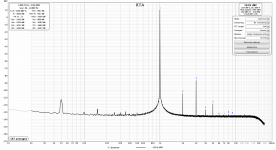
Here I show you an unpublished measurement of a DAO circlotron.
-115dB H2 and -97dB H3 at 1kHz 3Vrms into 50R.
All without any NFB.
I'll let the owner himself to pubish his full report once it is all finished.
From what I have seen so far, it is most probably the best headphone amp I know of.
Better than my own.
Patrick
.
Attachments
Since we are on the topics of unobtanium parts for the original circuit.
Recently John Broskie published a push-pull follower using a modulated current source (MCS).
In his case a LM337.
Push-pull Auto-Cathode-Bias and Error-Correcting MOSFET Output Stages
Well this is actually nothing new. For example, see EB602 MCS :
The Borbely EB602-200 Revisited
To reduce the number of LU1014's, as well as Toshiba MOSFETs, I had a look at using the MCS instead of the TCS.
You will then save a LU1014, and use a PMOS instead.
The attached is only for demo purposes only.
You can see that the MCS works quite well.
The bias current is set by the Vbe of Q1 and the sum of R13a & R13b.
The dynamic current ratio of M1, M2 is set by ratio of R13a / R13b.
DC offset can be adjusted via R12.
The distortion is not as good as the TCS, especially 2nd harmonics.
This is understandable, because the MCS simply duplicates the current of the Triode cell.
It does not perform any harmonic cancellation.
On top of that, thermal stability is likely to be worse due to different thermal drift of the JFET and the PMOS.
So the TCS is still better.
Cheers,
Patrick
.
Attachments
I have a bunch of tested and matched LU/LD1014 parts available here:
https://www.diyaudio.com/community/threads/ld1014d-lu1014d-matched-by-vgs-and-curve-tracing.381338/
https://www.diyaudio.com/community/threads/ld1014d-lu1014d-matched-by-vgs-and-curve-tracing.381338/
The testing and matching procedures are described in the thread:
https://www.diyaudio.com/community/threads/ld1014d-lu1014d-matched-by-vgs-and-curve-tracing.381338/
Let me know if something is not clear.
https://www.diyaudio.com/community/threads/ld1014d-lu1014d-matched-by-vgs-and-curve-tracing.381338/
Let me know if something is not clear.
Of course. It's no secret that if two parts are a good match at one operating point, they may not be an equally good match at other operating points. This is exactly why I added the curve traces so that one can check the matching across different operating points. If two parts have a matching set of curves, they will be a good overall match, not just at one operating point.A "perfect" matched pair at 1.5A is not so perfect ... at 200mA.
The 4CP-2511 (or 2500) would be a much better attenuator pretty much in the same price range.Since we are on the topic, the HAGS for the DAO SE can of course also take balanced input signal.
Two GB1 subscribers want to do exactly that.
So we designed a special PCB for them, shown here with TKD 4CP-601.
So, we use ventilation holes in the horizontal sinks as "compensation" for not having horizontal fins? Further reducing the sink surface... could be better.Note also the ventilation holes along the top edge of the heatsinks, hidden between the fins.
The amount of fine details is exemplary.
Kevin Gilmore's amps for dynamics pushing up to 35W with zero feedback or super symmetry, driving the HE-6 magnificently.Quite a few years ago, I was challenged to build an even higher power version of the DAO for the HE6.
Also recently there is a trend for headphone amps with power up to 8W.
So just for fun, I obliged.
Last edited:
Balanced DAO build in progress
After being under the radar for a couple of years the corona crisis finally gave me the time to finish my balanced DAO build. I'm still working on the case, but I hope to also round this up within the next month or so.
Picture shows the layout of the right channel amp core with the buffered X-feed circuit, Khozmo attenuator, voltage gain stage (HAGS), current buffer (DAO) and head phone protection circuit.
Now the finished article :
This balanced DAO is probably the lowest distortion headphone amp that does not have any global negative feedback.
Certainly one step further than that of Stixx, and even my own :
https://www.original-ton.net/amplifiers/dao/
https://www.diyaudio.com/community/...a-zgf-headphone-amplifier.225577/post-5405088
https://www.diyaudio.com/community/...a-zgf-headphone-amplifier.225577/post-5405093
I'll let Nic tell you the details.

Patrick
Hello,
I was bored and itching for a new PCB project and DAO caught my attention (something with LU1014, low distortion for HD800's, NGF, and EUVL's projects tend to be quite good). So here is my jank-DAO (the total antipode of the Stixx build).

I modified the schematic heavily to be adjustable, because i do not use any good matching at all. You will see the current sources are not the weird diodes (actually just simple jfet ccs in a diode package) i cant obtain, we can do better with few more components, why not.
The bottom ccs on original is taking current from output, but i did not trust this to work irl (and indeed it doesnt when you jumper it with J22), which is why i had it selectable with J22, of course now it runs pretty hot though.
The VDS adjustment directly taken from LuDEF (hope ZM doesn't mind), because they're not matched, and because i want to see effects of tweaking this on an FFT and selecting best operating point empirically.
Then we have 3.5ohm resistors with a pot, basically activated by jumper to either half, or precise-tweak all resistor values (simulation indicated there might be something to it, but in practice this was totally unecessary).
There is an optional crossfeed to play with, and the TCS is also optional (although for whatever reason it doesnt work at all for me, jumpering J20 or not produces no change at all in FFT).
The way i imagined the input stage is simply through daughterboards that press on top, seems to work fine.
While i was at it might as well add and SSR DC protection

PCB is pretty dense (especially considering its 91*52mm) and not that "pretty", there's a lot of these optional adjustment jumpers and such. But its 4 layer and logically laid out so it works just fine. Lu's are mounted underneath on alu board, not like shown on the render.

I was bored and itching for a new PCB project and DAO caught my attention (something with LU1014, low distortion for HD800's, NGF, and EUVL's projects tend to be quite good). So here is my jank-DAO (the total antipode of the Stixx build).
I modified the schematic heavily to be adjustable, because i do not use any good matching at all. You will see the current sources are not the weird diodes (actually just simple jfet ccs in a diode package) i cant obtain, we can do better with few more components, why not.
The bottom ccs on original is taking current from output, but i did not trust this to work irl (and indeed it doesnt when you jumper it with J22), which is why i had it selectable with J22, of course now it runs pretty hot though.
The VDS adjustment directly taken from LuDEF (hope ZM doesn't mind), because they're not matched, and because i want to see effects of tweaking this on an FFT and selecting best operating point empirically.
Then we have 3.5ohm resistors with a pot, basically activated by jumper to either half, or precise-tweak all resistor values (simulation indicated there might be something to it, but in practice this was totally unecessary).
There is an optional crossfeed to play with, and the TCS is also optional (although for whatever reason it doesnt work at all for me, jumpering J20 or not produces no change at all in FFT).
The way i imagined the input stage is simply through daughterboards that press on top, seems to work fine.
While i was at it might as well add and SSR DC protection
PCB is pretty dense (especially considering its 91*52mm) and not that "pretty", there's a lot of these optional adjustment jumpers and such. But its 4 layer and logically laid out so it works just fine. Lu's are mounted underneath on alu board, not like shown on the render.
For biasing the cascode Zener's; you can just use a resistor.
There is no need to use TO247 MOSFETs for the cascode.
And 15V rails are too limited when using 600R phones.
The PCB layout is obviously totally different from the original.
But DIY is about tailoring to one's own needs.
So the effort is still to be applauded.
Most important is that it pleases you.
Cheers,
Patrick
Hello, thanks for the comments. I want to bump your thread so i'll post some more stuff, i opened it up to plop in a superreg (yes its not supposed to be high current but it will see only about 10W per rail.. drop is only from +-20v to +-17v , so its only dissipating about 1.5W or so per pass transistor.
Most obvious thing i can notice going from the run of the mill opamp headphone driver HPA solutions is how much more slam this has, its not even volume, just more impact to it, it sounds a lot more dynamic. With the higher frequencies i wont comment because its in the realm of placebo for me, i think it sounds better but its not "immediately obvious" enough to comment on. It's a shame more people dont build this amp
Anyway, really does have a beautiful harmonic profile. Excuse the 50Hz peak, probably capacitatively coupling some wires due to thrown-together nature of the build..this is about 10db louder than i'd listen to on 102db/mw headphones.

Multitone is also nice, since its only a HP-amp, i just adjusted it to painful level and quickly unplugged, then gave it an extra 10db just to be safe, the grass is really low. (ignore the level variance, its some issue i have for a while with my setup, shows up on all sorts of amps.)

Some pics for vanity..

This shows my lazy LU1014 heatsinking solution, its just pressed on to the heatsink by the upper pcb


Most obvious thing i can notice going from the run of the mill opamp headphone driver HPA solutions is how much more slam this has, its not even volume, just more impact to it, it sounds a lot more dynamic. With the higher frequencies i wont comment because its in the realm of placebo for me, i think it sounds better but its not "immediately obvious" enough to comment on. It's a shame more people dont build this amp
Anyway, really does have a beautiful harmonic profile. Excuse the 50Hz peak, probably capacitatively coupling some wires due to thrown-together nature of the build..this is about 10db louder than i'd listen to on 102db/mw headphones.
Multitone is also nice, since its only a HP-amp, i just adjusted it to painful level and quickly unplugged, then gave it an extra 10db just to be safe, the grass is really low. (ignore the level variance, its some issue i have for a while with my setup, shows up on all sorts of amps.)
Some pics for vanity..
This shows my lazy LU1014 heatsinking solution, its just pressed on to the heatsink by the upper pcb
This is the level of distortion achieved by Stixx's Beta build, including HAGS gain stage :
https://www.diyaudio.com/community/...a-zgf-headphone-amplifier.225577/post-4879686
The balanced version is of course much lower.
Patrick
https://www.diyaudio.com/community/...a-zgf-headphone-amplifier.225577/post-4879686
The balanced version is of course much lower.
Patrick
Yeah, seems pretty inline then, cant remember off the top of my head what Vrms level my image corresponded to, somewhere around 1Vrms. Except you had a harder load (60R), while i had 300R resistor with "nominally 300R" headphones in parallel, and it also agreed with the sims in my case as well, so nothing controversial. Unless i'm missing something?
N+D= -91.3 dbfs
Your words from post you linked:
Nothing on the image is -70db even, if nothing else, it requires some elaboration what you're looking at, if not the REW image i posted.
Also 300 with 300 in parallel =/= 300
though still a lighter load, as you know, this amp improves measurement-wise with a bit higher load, so its a bit reverse situation than normal amps. When i remove the 300R it gets slightly worse, not sure where optimal point is. I added it primarily to avoid zobel and have the amp see a load at all times, I have not experimented yet but maybe i could try lowering it, you said yourself you optimised for 60R HE-6's.
P.S my source and ADC are 150$ interface (good enough for me), with their own distortions superimposed and not AP system, so real performance is even a bit better, but ok.
Your words from post you linked:
On image we see: almost entirely 2nd harmonics @ around -91db, 3rd and 4th below -115.output amplitude of 1.2Vrms, distortion through the entire amp (XFD, HAGS, DAO) was -90dB.
It was entirely 2nd harmonics. 3rd and 4th were below noise level at -110dB.
Nothing on the image is -70db even, if nothing else, it requires some elaboration what you're looking at, if not the REW image i posted.
Also 300 with 300 in parallel =/= 300
though still a lighter load, as you know, this amp improves measurement-wise with a bit higher load, so its a bit reverse situation than normal amps. When i remove the 300R it gets slightly worse, not sure where optimal point is. I added it primarily to avoid zobel and have the amp see a load at all times, I have not experimented yet but maybe i could try lowering it, you said yourself you optimised for 60R HE-6's.
P.S my source and ADC are 150$ interface (good enough for me), with their own distortions superimposed and not AP system, so real performance is even a bit better, but ok.
- Home
- Amplifiers
- Headphone Systems
- The DAO SE all-FET Class-A ZGF Headphone Amplifier