I checked out the website of Hifiman.
They specify 6W at 50R. That converts to +/-25V out, 0.5A.
For a power amp to offer low distortion at that level, you are likely to need +/- 35V rails, 0.8A bias.
You can easily build an F5 for that, using one pair of 2SK1530/2SJ201.
Or 3 pairs of 2SK2013/2SJ313 in parallel.
It would be a global-feedback amp, but it would probably still sound nice.
It is already widely published in the Pass forum. So I suggest you refer to those threads.
Of course you can also use a CFP buffer to lower distortion, like a few BUF634s in parallel.
Also widely discussed elsewhere.
So plenty of choice, including the 3x DAO as described in the previous post.")
Patrick
They specify 6W at 50R. That converts to +/-25V out, 0.5A.
For a power amp to offer low distortion at that level, you are likely to need +/- 35V rails, 0.8A bias.
You can easily build an F5 for that, using one pair of 2SK1530/2SJ201.
Or 3 pairs of 2SK2013/2SJ313 in parallel.
It would be a global-feedback amp, but it would probably still sound nice.
It is already widely published in the Pass forum. So I suggest you refer to those threads.
Of course you can also use a CFP buffer to lower distortion, like a few BUF634s in parallel.
Also widely discussed elsewhere.
So plenty of choice, including the 3x DAO as described in the previous post.
Patrick
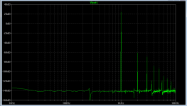
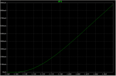
My estimates in post #40 is pretty accurate, at least according to LT Spice.
3 pairs of JFETs with total bias of 600mA. +/-35V rails.
Input signal +/-25V 1kHz sine.
Patrick
3 pairs of JFETs with total bias of 600mA. +/-35V rails.
Input signal +/-25V 1kHz sine.
Patrick
Attachments
Last edited:
My estimates in post #40 is pretty accurate, at least according to LT Spice.
3 pairs of JFETs with total bias of 600mA. +/-35V rails.
Input signal +/-25V 1kHz sine.
Patrick
Thankyou for sharing this, I really like that you are offering a buffer headphone design because really that's whats needed with all headphones it seems all headphone "amp designs always come down to the output stage." If you are a tube guy like me this DOA-SE is exciting stuff because finding output Iron for headphones is frustrating at best. I had a StackerII which was an interesting design but had glaring flaws, this is simple, elegant and output capacitor/dc servo free
I've listened to a lot of headphones over the years and these hifiman's are a PITA to build an amp for but they are worth it (currently using a commercial hybrid design with a lot of compromises). I think the other orthos are hard to drive as well. I'm not a hifman nut job just addicted to their sound so when I see a company like AN designing an amp for them I know others out there are placing these high on the headphone "totem" pole.
I guess if I dropped the tube stage ideal and drove these balanced with your gain stage using the +-35V rails with the buffer I could reasonably expect to get away with one Jfet. I think it would be tough to parallel 3 because of the matching required? Plus with all the input capacitance of paralleled jfets it would ruin a tube gain stage anyway.
Thanksagain have a good holiday

PS the 6W sim you posted is better than a F4 or Moskido for 6W into 50 ohms
Last edited:
Give me a day.
I'll find a special solution for your HE-6 (other than using 6 LU1014s per channel).
But it will burn heat, and need large heat sinks.
Patrick
No hurry at all Patrick, its not just for me there's a bunch of us ortho addicts.
Thanks again.
Actually it is done.
If I had to do this for myself, then I would not consider using the DAO for this particular application.
As already show in post 42, you can use 3x DAO in parallel to achieve very decent performance.
The price is high dissipation, as this is the brute force approach.
You can combine the gain stage and the buffer into one by using a F5X-Mini.
3 pairs of 2SK2013/2SJ313 as output devices.
But this is a global feedback amp.
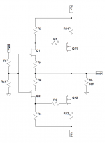
Or you can use the attached circuit.
It is essentially a JFET / MOSFET CFP buffer, similar to the John Linsley Hood Buffer but with MOSFETs at the output.
1st stage is 2SK170/2SJ74 at about 8mA bias.
2nd stage can be 3 pairs of 2SK2013/2SJ313 with a total bias of 350mA.
Rail voltage is +/-25V.
THD at +/-20V 1kHz sine on 50 ohm load is below -80dB.
The local feedback of the CFP is responsible for the low distortion despite the low bias.
Easy enough to wire P2P.
Dissipation per channel about 18W, so you need a larger heat sink than the one shown in post#1 (That will only do about 20W).
But 18W is still about half of 3x DAO in parallel.
Only simulated, so build at own risk.
You can email me for more details, if you are serious about building.
Patrick
If I had to do this for myself, then I would not consider using the DAO for this particular application.
As already show in post 42, you can use 3x DAO in parallel to achieve very decent performance.
The price is high dissipation, as this is the brute force approach.
You can combine the gain stage and the buffer into one by using a F5X-Mini.
3 pairs of 2SK2013/2SJ313 as output devices.
But this is a global feedback amp.
Or you can use the attached circuit.
It is essentially a JFET / MOSFET CFP buffer, similar to the John Linsley Hood Buffer but with MOSFETs at the output.
1st stage is 2SK170/2SJ74 at about 8mA bias.
2nd stage can be 3 pairs of 2SK2013/2SJ313 with a total bias of 350mA.
Rail voltage is +/-25V.
THD at +/-20V 1kHz sine on 50 ohm load is below -80dB.
The local feedback of the CFP is responsible for the low distortion despite the low bias.
Easy enough to wire P2P.
Dissipation per channel about 18W, so you need a larger heat sink than the one shown in post#1 (That will only do about 20W).
But 18W is still about half of 3x DAO in parallel.
Only simulated, so build at own risk.
You can email me for more details, if you are serious about building.
Patrick
Attachments
Regal,
I have not heard the HE-6, but I am sure you have and are aware of these measurements?
http://www.innerfidelity.com/images/HiFiMANHE6.pdf
And perhaps also this :
6moons audio reviews: HifiMan EF6
(essentially a mini power amp)
Must have a very warm feeling with 5W close to your ears.
As a challenge for myself, I'll think of a solution with 1 pair of LU1014s per channel.
Will let you know when it is ready.
Patrick
Last edited:
I own an older similar model the HE-5LE's and just love their sound they need 2W's at 38 ohm (similar to the HE-500's). I'm just looking at this from a bigger perspective : if AudioNote builds an amp for a headphone that's a challenge for diyers like us
I did read on the first page of inner fidelity you linked =
Euvl, maybe a more reasonable target would be the HE-500 and LCD-3's. The main thing is flexibility. A lot of us like inefficient antique AKG 600 ohm headphones too ( they need a good 11Vrms and 150mA of current.)
I did read on the first page of inner fidelity you linked =
Steve Guttenberg and I have gone back and forth on whether measurements are useful to consumers, but we both agree that the measurements don't tell you whether it's a good headphone or a great one.
Euvl, maybe a more reasonable target would be the HE-500 and LCD-3's. The main thing is flexibility. A lot of us like inefficient antique AKG 600 ohm headphones too ( they need a good 11Vrms and 150mA of current.)
Last edited:
A version of the DAO as it is will do 11Vrms and 150mA.
It will be described in Part 2b of the article (after Xmas).
So I consider the AKG 600 covered.
The HE-6 I also now considered solved, at least in simulation, using 5 active devices per channel.
The driver device is still an LU1014, cascoded by a higher power MOSFET.
The trick is then to get the LU1014 to work in triode mode at a bias of ~500mA.
In simulation, at full +/-25V swing into 50 ohm load, 2nd harmonics is -85dB, 3rd -100dB, 4th -105dB.
Bandwidth -3dB is 2MHz.
That is respectable performance, even only in simulation.
The changes are not minor, so we need new PCBs as well as a substantially revised case design.
But since headphone is not our main interest, I doubt we should invest 1300 USD to buy one of these just for testing.
Unless of course there is a huge interest (so far only you ?).
If you wish to take the risk and do alpha test, we might consider to support you technically.
But it is a lot of work for us, and for you, since it is not a "made bed", so to say.
You may email me for more details.
Patrick
A version of the DAO as it is will do 11Vrms and 150mA.
It will be described in Part 2b of the article (after Xmas).
So I consider the AKG 600 covered.
The HE-6 I also now considered solved, at least in simulation, using 5 active devices per channel.
The driver device is still an LU1014, cascoded by a higher power MOSFET.
The trick is then to get the LU1014 to work in triode mode at a bias of ~500mA.
In simulation, at full +/-25V swing into 50 ohm load, 2nd harmonics is -85dB, 3rd -100dB, 4th -105dB.
Bandwidth -3dB is 2MHz.
That is respectable performance, even only in simulation.
The changes are not minor, so we need new PCBs as well as a substantially revised case design.
But since headphone is not our main interest, I doubt we should invest 1300 USD to buy one of these just for testing.
Unless of course there is a huge interest (so far only you ?).
2
But i'm interested in lower voltage, higher current to drive 25-80 ohm HPs only.
How do you define "high" current ?
Is 200mA Class A insufficient ?
The original DAO was designed for the AKGK701 at 62 ohm, which is about the middle of your mentioned range.
On top of that, I have not finished published all parts of the article.
For example, in Part 2b, higher current and higher voltage versions would be dealt with.
The HE-6 is a special case.
I do not know any other headphone that needs 6W, other than maybe the electrostatics.
That is why it needs special treatment.
Maybe a bit more patience, and your "problem" might be resolved automatically.
Merry Christmas,
Patrick
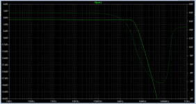
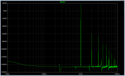
I have been asked to show a simulated FFT plot of the HCLI (High Current Low Impedance) version as described in Part 2b.
Here it is, with 22V p-p output into 40 ohm.
I consider harmonics < -80dB at such output levels to be very respectable for a headamp.
Especially achieved just by a JFET source follower with ZGF.
Patrick
Here it is, with 22V p-p output into 40 ohm.
I consider harmonics < -80dB at such output levels to be very respectable for a headamp.
Especially achieved just by a JFET source follower with ZGF.
Patrick
Attachments
I have been asked to show a simulated FFT plot of the HCLI (High Current Low Impedance) version as described in Part 2b.
Here it is, with 22V p-p output into 40 ohm.
I consider harmonics < -80dB at such output levels to be very respectable for a headamp.
Especially achieved just by a JFET source follower with ZGF.
Patrick
Hmmm
Can you post a plot with 4V output?
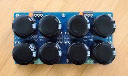
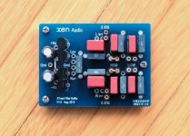
Part 3 of the article, plus a couple of finished PCBs.
In case you wonder why the amp PCB has not been shown, I have been waiting for PRP resistors from the US for 2 months !!!!
Patrick
.
In case you wonder why the amp PCB has not been shown, I have been waiting for PRP resistors from the US for 2 months !!!!
Patrick
.
Attachments
- Home
- Amplifiers
- Headphone Systems
- The DAO SE all-FET Class-A ZGF Headphone Amplifier