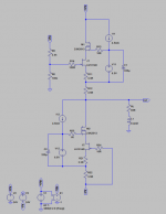
For performance.
Also bias is now lower (almost halved), so no need to use TO247.
Patrick
cool! I did wonder how you were coming up with the 15W figure; much lower than what I experienced lol, more appropriate for a headphone buffer. I have some newly received R125 that are destined for an F6, but I may throw them in a quick lash up of an all jfet version of the DAO for fun

I guess you tried the semisouth and decided against them for some reason, but thats no reason for me not to try them.
it really is an elegant circuit; kudos!
for those DIYers not too lazy to reterminate their headphones, but too lazy to recable them?
no, for those that want to use a stock headphone cable AND stock termination on a balanced bridged amp.
Last edited:
huh? how does that work, you bring ground out to an adapter? i'm confused, since i've not ever seen a stock headphone with a 5 pin XLR on it. or you are talking about using 2 x neutrik combo jacks? and 5 pin stands for 3 pin XLR + the 2 extra contacts needed to fill out the phono?
huh? how does that work, you bring ground out to an adapter?
right. So, connect ground to one of the 5 pins on the amplifier jack, build an adaptor. The only way possible to connect a three wire headphone to a balanced bridged amp that allows use of stock cable and stock termination. I do that rather than add a second jack to the amp, for reasons stated above.
This way, dynamic 'phones don't have an "extra pin complex" over their electrostatic cousins
Last edited:
Ah.. OK hmm. i'm at a loss for an opinion on that... (gasp, the crowd goes quiet )
me, I just recable the headphones as the path of least resistance...obviously =) and use 4 pin on everything Balanced or SE. Having a dedicated return for each driver is always beneficial IMO.
the DT1350 posted above are a result of that, they were the original single side entry/J-cable version modified for dual entry balanced. Doesnt help the fact that they are pathologically microphonic no matter what cable or sleeving is used...truly its unbelievable!
)me, I just recable the headphones as the path of least resistance...obviously =) and use 4 pin on everything Balanced or SE. Having a dedicated return for each driver is always beneficial IMO.
the DT1350 posted above are a result of that, they were the original single side entry/J-cable version modified for dual entry balanced. Doesnt help the fact that they are pathologically microphonic no matter what cable or sleeving is used...truly its unbelievable!
Last edited:
fair enough.
I ended up using a jfet CCS in place of the CRD, as the alternative parts are in short supply at mouser and ridiculously priced at Farnell.
oh hang on, its listed as new stock at mouser E-452
when I was collecting parts it wasnt easy to come by and the 1N53XX were prohibitively expensive (still are at nearly $8 each)
I've been trying to simulate this and not getting good results. With a typical 1khz fft it has a ton of distortion I am sure it is me. Has anyone had any success with LTSpice?
This looks like just what a lot of us need need. I need a buffer that can handle headphones like the HE-6 and the HE-5LE, these headphones sound great but are a B*th to drive Been thinking about a classic all DHT SET-OPT but it would make much more sense to build a DHT gain stage and use this for the buffer, but I like to run simulation to get a feel for how much power it can deliver into a ~40 ohm headphone. I am also thinking this would give a good bit of 2H & 3H cancelation when driven by a tube "preamp" since it essentially behaves like a triode.
I need the simulation I think because running single ended probably makes most sense if using an SET gain stage so I would have to push the limits a bit for these dam ortho headphones I adore.
Any way we look at it this is an exciting alternative as a hybrid for orthos. Thanks for starting this project.
This looks like just what a lot of us need need. I need a buffer that can handle headphones like the HE-6 and the HE-5LE, these headphones sound great but are a B*th to drive
Been thinking about a classic all DHT SET-OPT but it would make much more sense to build a DHT gain stage and use this for the buffer, but I like to run simulation to get a feel for how much power it can deliver into a ~40 ohm headphone. I am also thinking this would give a good bit of 2H & 3H cancelation when driven by a tube "preamp" since it essentially behaves like a triode. I need the simulation I think because running single ended probably makes most sense if using an SET gain stage so I would have to push the limits a bit for these dam ortho headphones I adore.
Any way we look at it this is an exciting alternative as a hybrid for orthos. Thanks for starting this project.
We don't realise our Spice models, but I can show you our results, just to prove.
We also use our own simulation tools which allow us to use actual measured data in the calculations.
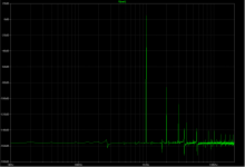
-90dB for 2Vrms output I consider quite decent for a ZGF circuit driving 65R output.
Patrick
We also use our own simulation tools which allow us to use actual measured data in the calculations.
-90dB for 2Vrms output I consider quite decent for a ZGF circuit driving 65R output.
Patrick
Attachments
Last edited:
We don't realise our Spice models, but I can show you our results, just to prove.
We also use our own simulation tools which allow us to use actual measured data in the calculations.
-90dB for 2Vrms output I consider quite decent for a ZGF circuit driving 65R output.
Patrick
That is good ! However see that AudioNote just released a headphone amp specifically for the HifiMan HE6. These are the headphones to be striving for design wise. May want to look at increasing supply rails and bias as an option, you want low distortion up to 8Vrms into 40-50 ohms. Just a suggestion.
You mean this Audio Note Kits -HE-6 Headphone Amplifier ?
Isn't it essentially a 9W Class A Tube Amp adapted to drive a 50 ohm load by matching the impedance of the output transformer ? I cannot find any THD spec. But I guess if it can drive a small loudspeaker to 9W Class A, it can also drive a 50ohm load with low enough distortion at 8Vrms, when it is impedance matched. It is perhaps worth noting that it has a output transformer in the signal path (without feedback ?) and without feedback. I don't know transformer enough to use one of those, but I wonder what the open loop distortion of the transformer might be at 8Vrms ?
Of course if you use a low-power F5 (2SK2013 / 2SJ313) to drive a 50ohm headphone, you will also achieve very decent performance, at least very decent THD figures. But a mini power amp is not what I intend to offer here.
The DAO will drive a 30ohm load quite happily, but not to 2W output. However the basic circuit is published. And you are most welcome to experiment with increasing number of devices, bias, voltages, etc.
Regards,
Patrick
You mean this Audio Note Kits -HE-6 Headphone Amplifier ?
Isn't it essentially a 9W Class A Tube Amp adapted to drive a 50 ohm load by matching the impedance of the output transformer ? I cannot find any THD spec. But I guess if it can drive a small loudspeaker to 9W Class A, it can also drive a 50ohm load with low enough distortion at 8Vrms, when it is impedance matched. It is perhaps worth noting that it has a output transformer in the signal path (without feedback ?) and without feedback. I don't know transformer enough to use one of those, but I wonder what the open loop distortion of the transformer might be at 8Vrms ?
Of course if you use a low-power F5 (2SK2013 / 2SJ313) to drive a 50ohm headphone, you will also achieve very decent performance, at least very decent THD figures. But a mini power amp is not what I intend to offer here.
The DAO will drive a 30ohm load quite happily, but not to 2W output. However the basic circuit is published. And you are most welcome to experiment with increasing number of devices, bias, voltages, etc.
Regards,
Patrick
I didn't mean to compare your elegant design to AN, just to point out that if they are marketing an amp for HE-6's its a bit of a big deal, MHO is the new hard to drive orthos are a game changer in the headphone world so if we could experiment with your buffer design it would be beneficial to you and those of us with orthos.
I like to start from a sim before I build, I'll spend some more time on it and see how feasible it is to get more power but you certainly know more about these power jfets than me
 .
.Thanks
You have only seen 2 parts of the document, and there are 4 more parts to come.
But already you can seen that per JFET, the useful current range is probably not more than 100mA before distortion increases.
So if you want to drive 50 ohm to 8Vrms (although I also cannot understand why you want 2W next to your ears), your current output has to be about 240mA.
That means 3 pairs of FETs in parallel.
Your bandwidth will drop by a factor of 3, because of increased capacitances.
You can increase voltage slightly to say 32V.
The 2SK2013 that cascodes each LU1014 will do OK with that.
Else you can also use 2SK1529 with slightly different component values.
And of course your dissipation will go up to about 76W for two channels.
Then I expect you to get THD below -80dB.
Hope this helps your specific wishes,
Patrick
Last edited:
- Home
- Amplifiers
- Headphone Systems
- The DAO SE all-FET Class-A ZGF Headphone Amplifier