Hey all! After stalking the DIY Audio forums for a few years, I finally have something to show for myself.
I'm putting together a headphone amp and I wanted to take advantage of my DAC's balanced outputs, so with a little research and tinkering I came up with this design. There are a few things that I'm going to change in the final design, but this is the gist of it.
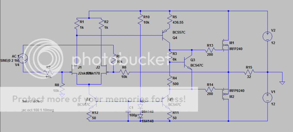
- The values shown have it set to unity gain which i may tweak, but my DAC puts out 2Vrms so i doubt i'll need any gain.
- I'm going to use IRF510/IRF9510 output MOSFETS. The schematic shows IRFP240/9240 as those were the only complementary pairs i could find in LTSpice. I will adjust the Vbe Multiplier and bias current in the final design.
Now a few questions for those of you out there who now what they are doing (I'm a second year EE undergrad, so my knowledge is a bit limited):
-Is there anything blatantly wrong with this design? It may not be the most effective design, but it's relatively simple and uses parts that I have.
-What bias current should I use? I have a pair of Grado SR125's, 32Ohm. I've seen bias currents all over the place, even as high as 100mA.
- Any suggestions for better output mosfets? I've seen irf510's used fairly often and have played with them a fair bit myself, and am pretty comfortable with them, but I've also seen all sorts of exotic things used on this forum so I'm open to suggestions.
Schematic:
If someone would like I can post an FFT plot.
I'm putting together a headphone amp and I wanted to take advantage of my DAC's balanced outputs, so with a little research and tinkering I came up with this design. There are a few things that I'm going to change in the final design, but this is the gist of it.
- The values shown have it set to unity gain which i may tweak, but my DAC puts out 2Vrms so i doubt i'll need any gain.
- I'm going to use IRF510/IRF9510 output MOSFETS. The schematic shows IRFP240/9240 as those were the only complementary pairs i could find in LTSpice. I will adjust the Vbe Multiplier and bias current in the final design.
Now a few questions for those of you out there who now what they are doing (I'm a second year EE undergrad, so my knowledge is a bit limited):
-Is there anything blatantly wrong with this design? It may not be the most effective design, but it's relatively simple and uses parts that I have.
-What bias current should I use? I have a pair of Grado SR125's, 32Ohm. I've seen bias currents all over the place, even as high as 100mA.
- Any suggestions for better output mosfets? I've seen irf510's used fairly often and have played with them a fair bit myself, and am pretty comfortable with them, but I've also seen all sorts of exotic things used on this forum so I'm open to suggestions.
Schematic:
If someone would like I can post an FFT plot.
you can attach the .asc to your post as well for people to poke at
you can zip your added device models, or just put the defs on the schematic with the spice directive cmd ( .op far right on tool bar )
mosfets require a fair amount of bias, parasitic capacitances behave poorly when they have < ~ 2x Vt across their D-S so I would use higher supply V even though Grado headphones don't require that much V
I expect the amp is ~ single pole compensated by the parasitic C of the output devices - which as I mentioned is a function of D-S V - it can work but may make the amp very sensitive to parts choice, operating point - and the mosfet spice models may not show this very well
Here's the .asc
I included the 2sk170 as a directive, everything else should be in the standard LTSpice library.
Unfortunately I'm limited by supply voltage, since I already have a 2x 12V toroidal transformer and don't have money for a different one (ah, the life of a student). I know the rectified voltage is higher and all, but with rectifier losses and regulator drop I'm not sure how much higher I can get the supply voltage. I've used irf510's at 12V before and they didn't present much of a problem. With careful layout I think they'll be fine.
View attachment HeadAmp.zip
- Status
- This old topic is closed. If you want to reopen this topic, contact a moderator using the "Report Post" button.