How to build an Objective2 Headphone amplifier.
This is such an awesome project that I hope that someone might see this and 'get off the fence' and build one. It's a great first project, but it has such fantastic performance that even the most diehard DIYer will be extremely pleased with it.
If you are not familiar with the O2, here is some more information -
NwAvGuy: O2 Headphone Amp
And this link has all the really good information in it for the DIY constructor -
NwAvGuy: O2 Details
One of the reasons that this project is so good, other than it's very good design, is that it is documented better than just about any other DIY project ever. Just about all your questions are answered by the designer himself. It is wonderfully beneficial to read the above all the way through before starting construction.
This is my visual build log for the O2.
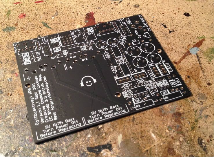
This is the board in it's empty state.
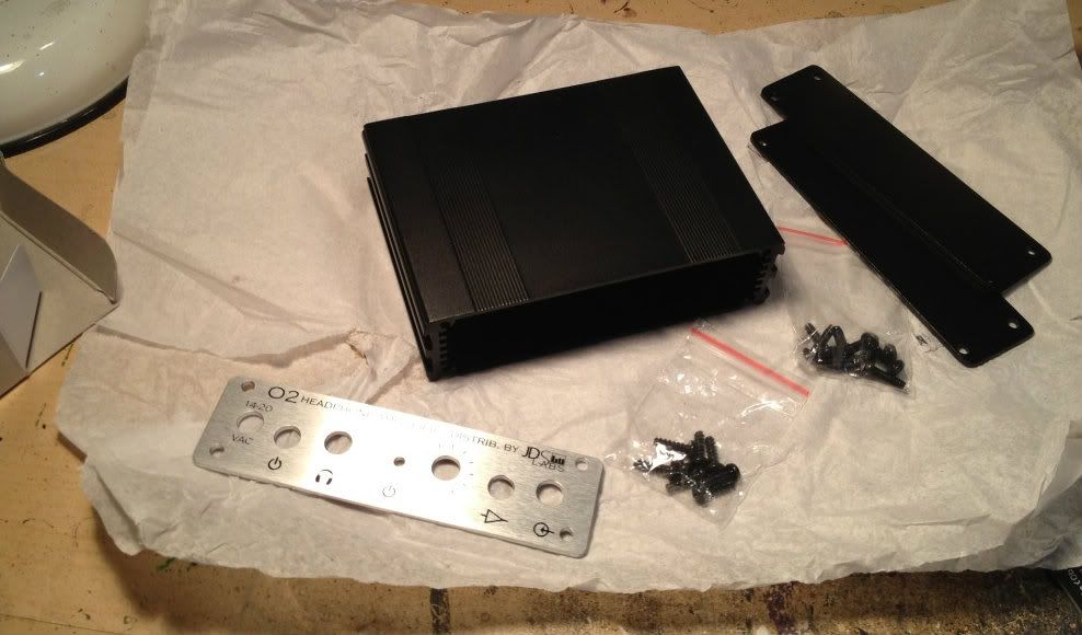
The Box Enclosures box and the faceplate, purchased from JDS labs. See this page -- JDS Labs - Store - DIY Parts
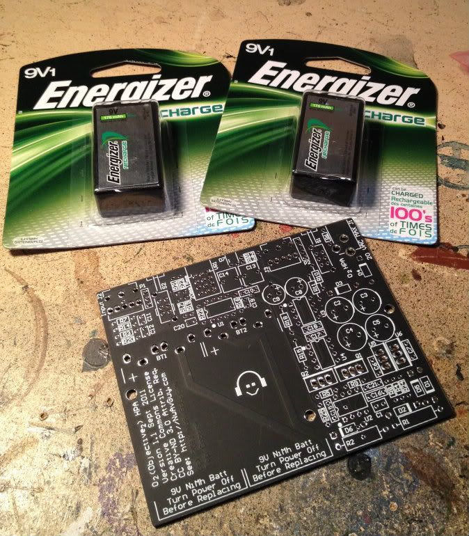
Here is a good photo for scale, 2 normal 9v batteries.
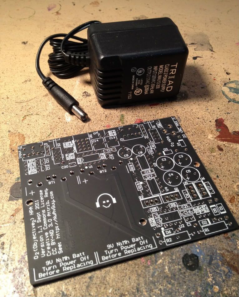
And this is the small AC wall-wart for charging or playing. With the amp playing on either the AC supply or the internal DC batteries, it sounds the same.
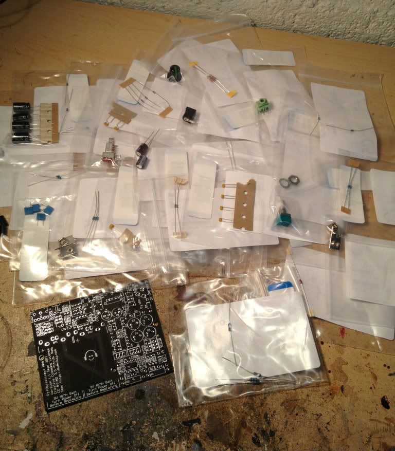
Some (but not all) of the various components to go on the board.
That is everything sans enclosure and batteries.
It is absolutely imperative that you check and double check the locations of the items as you stuff the board, and measure everything that you have the capability to measure before installing it.
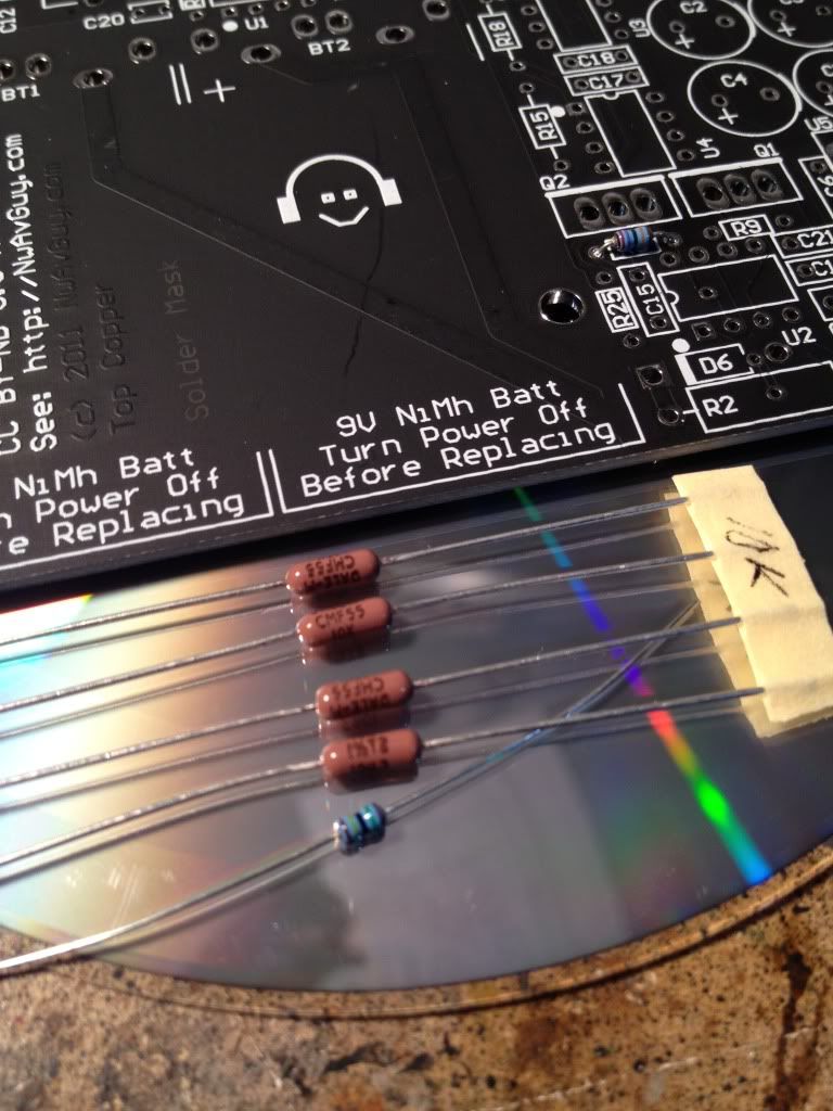
Most of the specified resistors are these cute tiny 1/8 watt items, shown with a 'normal' 1/4 watt Dale for comparison. Also look at the PCB and see one installed. You don't want to remove one of these if you don't have to.
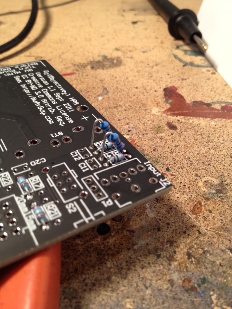
I made one error when ordering, where I entered a quantity of one when I needed two. So I replaced both with a bigger (1/4w) resistor, seen here mounted 'soldier style.'
If you have bunch of 1/4w resistors on hand I see no reason why you couldn't use them mounted as such in all the locations where a 1/8w would go. There is plenty of room.
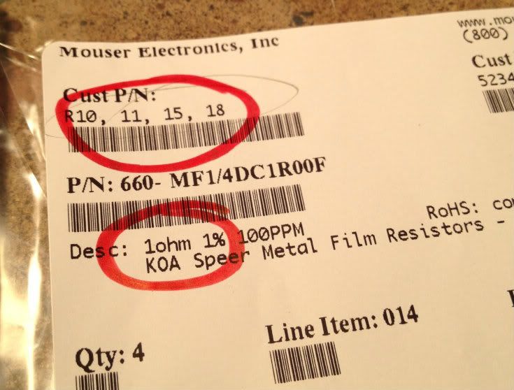
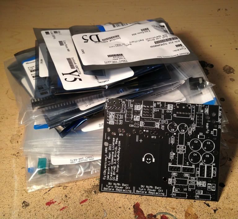
I ordered my parts from Mouser, merely copy and pasting from the published BOM into the order page on Mouser's site. When you order, there is a place for you to enter a 'customer part number' which is a great time to label the parts to match the board.
The 2 circles are my pattern to cut down on stuffing errors - the top circle is to match the part description against the BOM. The bottom circle is to verify the value printed matches what I measure it to be. It doesn't take much time, and cuts errors way down.")
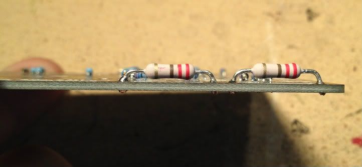
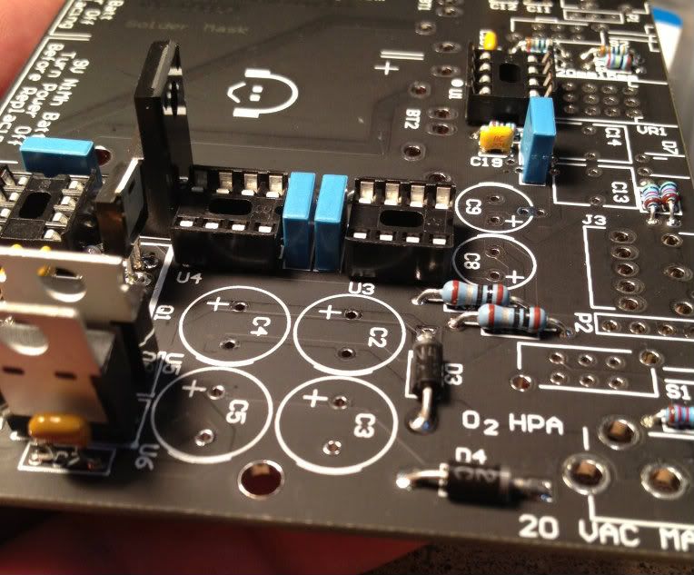
It's always a good idea to leave a bit of room between the board and PSU filter resistors. They get hotter than the other resistors.
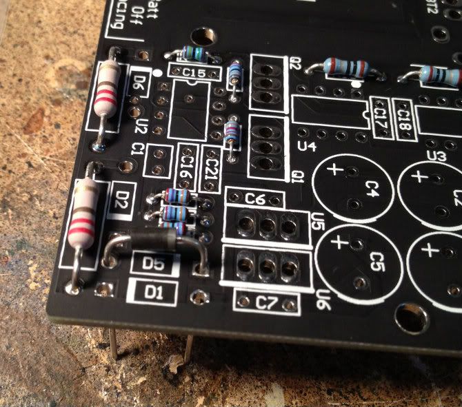
Diodes match the board, put the striped end (of the diode) on the striped end.(of the board)
I forgot to take a photo with just the resistors and nothing else. Oh well… The ceramic caps (the yellowish ones) are next. As always, we will stuff the board smallest items first, then the next bigger, and so on.
The next components are the blue film caps and the DIP sockets. (for the opamps)
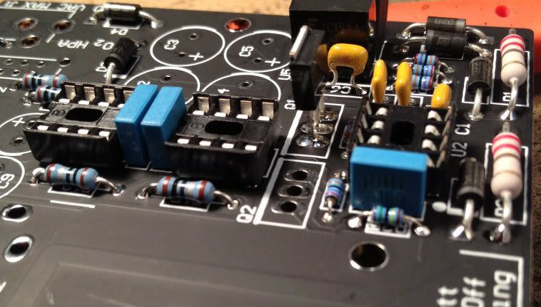
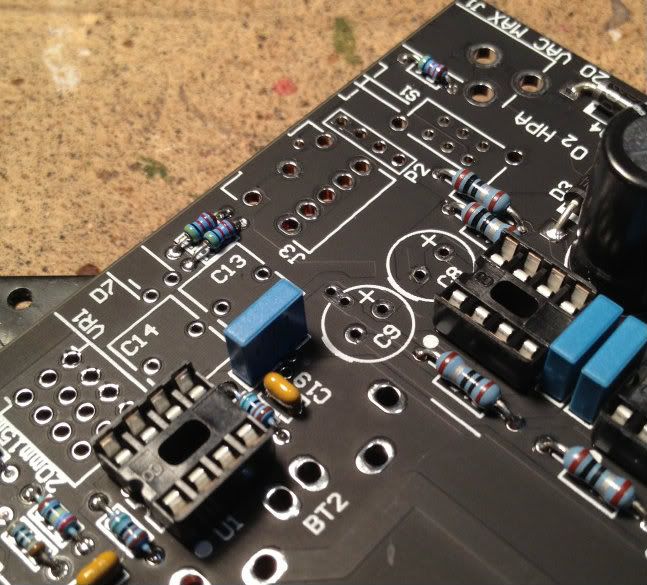
The regulator pieces are next, they are also polarized, the heavy white line of the board shows the back (tall and or flat) side of the power devices.
And there is the proper orientation of the device.
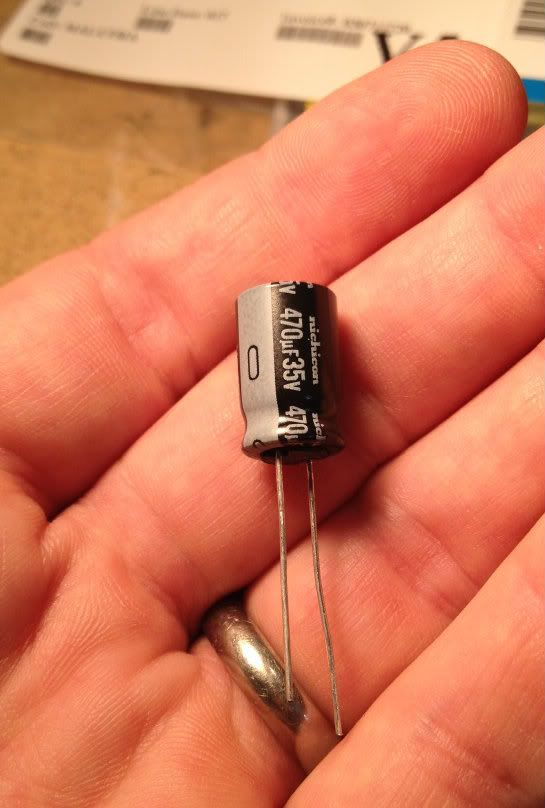
The can capacitors have the potential to blow up if installed improperly. They are polarized, and even marked twice -- the long lead is the positive, and the stripe with the " - " sign is the negative.
The pads for the caps are also well marked, the + is clearly visible, and also you can see the bit of heavier line on the circle, to mark the negative. That's a very nice touch.
Again, where you have a can cap, you will see those markings.
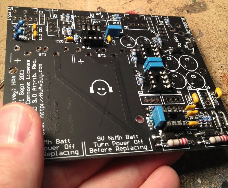
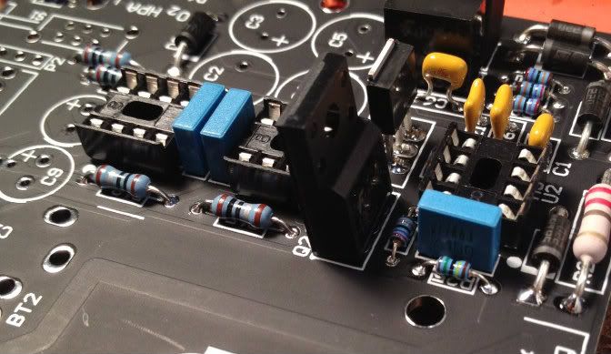
By this time you should have the bulk of the board stuffed minus the edge with all the jacks.
The AC plug supplied didn't quite fit the holes in the board. The supplier probably made a change recently without telling anybody. Oh well. You can see where I filed the connection down, to let it fit smoothly on the PCB.
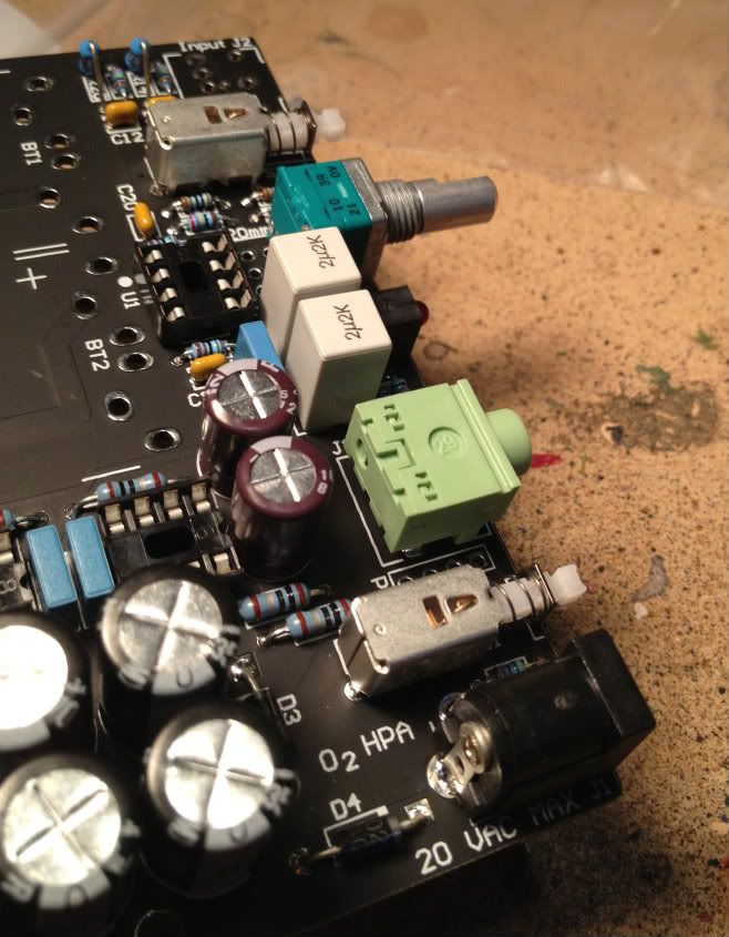
It seemed the most logical to stuff the components on the edge from the bottom to the top. It worked well, and nothing interfered with anything else. Easy!
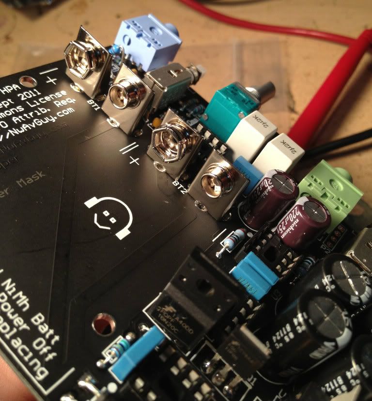
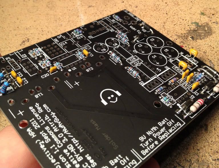
In every photo of the PCB on NwAvGuy's site, the watermark completely obscures the battery terminals! Anyway, it is supposed to look like this.
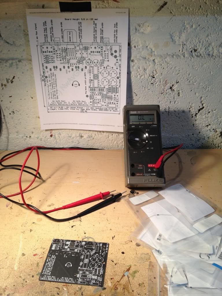
At this point you are ready to do some testing. Go to this page - NwAvGuy: O2 Details Scroll down to the photo of the Multimeter and start the testing procedure!
~~~~~~~~~~~~~~~~~~
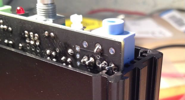
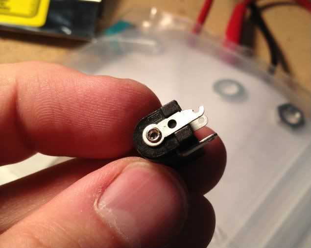
As mentioned in the build guide, if the solder pins are not cleanly trimmed it will snag on the case. However don't remove the center front pin because…
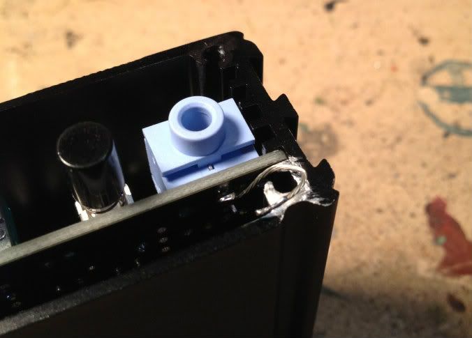
You need to attach a wire to it to attach to a bare parch of the case via a panel screw. A thin wire or a trimmed component lead will do nicely here.
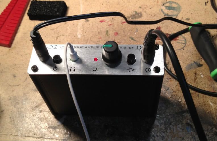
Here is the O2 playing music for the very first time. It looks great! Interestingly, my phone was playing the music and taking the photo… Cool.
The O2 is completely silent and sounds fantastic!
EDIT -
Here is my amp with a Stainless Steel faceplate from member 'Yangoran'
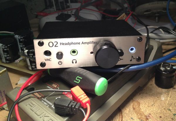
It looks great!!
This is such an awesome project that I hope that someone might see this and 'get off the fence' and build one. It's a great first project, but it has such fantastic performance that even the most diehard DIYer will be extremely pleased with it.
If you are not familiar with the O2, here is some more information -
NwAvGuy: O2 Headphone Amp
And this link has all the really good information in it for the DIY constructor -
NwAvGuy: O2 Details
One of the reasons that this project is so good, other than it's very good design, is that it is documented better than just about any other DIY project ever. Just about all your questions are answered by the designer himself. It is wonderfully beneficial to read the above all the way through before starting construction.
This is my visual build log for the O2.
This is the board in it's empty state.
The Box Enclosures box and the faceplate, purchased from JDS labs. See this page -- JDS Labs - Store - DIY Parts
Here is a good photo for scale, 2 normal 9v batteries.
And this is the small AC wall-wart for charging or playing. With the amp playing on either the AC supply or the internal DC batteries, it sounds the same.
Some (but not all) of the various components to go on the board.
That is everything sans enclosure and batteries.
It is absolutely imperative that you check and double check the locations of the items as you stuff the board, and measure everything that you have the capability to measure before installing it.
Most of the specified resistors are these cute tiny 1/8 watt items, shown with a 'normal' 1/4 watt Dale for comparison. Also look at the PCB and see one installed. You don't want to remove one of these if you don't have to.
I made one error when ordering, where I entered a quantity of one when I needed two. So I replaced both with a bigger (1/4w) resistor, seen here mounted 'soldier style.'
If you have bunch of 1/4w resistors on hand I see no reason why you couldn't use them mounted as such in all the locations where a 1/8w would go. There is plenty of room.
I ordered my parts from Mouser, merely copy and pasting from the published BOM into the order page on Mouser's site. When you order, there is a place for you to enter a 'customer part number' which is a great time to label the parts to match the board.
The 2 circles are my pattern to cut down on stuffing errors - the top circle is to match the part description against the BOM. The bottom circle is to verify the value printed matches what I measure it to be. It doesn't take much time, and cuts errors way down.
It's always a good idea to leave a bit of room between the board and PSU filter resistors. They get hotter than the other resistors.
Diodes match the board, put the striped end (of the diode) on the striped end.(of the board)
I forgot to take a photo with just the resistors and nothing else. Oh well… The ceramic caps (the yellowish ones) are next. As always, we will stuff the board smallest items first, then the next bigger, and so on.
The next components are the blue film caps and the DIP sockets. (for the opamps)
The regulator pieces are next, they are also polarized, the heavy white line of the board shows the back (tall and or flat) side of the power devices.
And there is the proper orientation of the device.
The can capacitors have the potential to blow up if installed improperly. They are polarized, and even marked twice -- the long lead is the positive, and the stripe with the " - " sign is the negative.
The pads for the caps are also well marked, the + is clearly visible, and also you can see the bit of heavier line on the circle, to mark the negative. That's a very nice touch.
Again, where you have a can cap, you will see those markings.
By this time you should have the bulk of the board stuffed minus the edge with all the jacks.
The AC plug supplied didn't quite fit the holes in the board. The supplier probably made a change recently without telling anybody. Oh well. You can see where I filed the connection down, to let it fit smoothly on the PCB.
It seemed the most logical to stuff the components on the edge from the bottom to the top. It worked well, and nothing interfered with anything else. Easy!
In every photo of the PCB on NwAvGuy's site, the watermark completely obscures the battery terminals! Anyway, it is supposed to look like this.
At this point you are ready to do some testing. Go to this page - NwAvGuy: O2 Details Scroll down to the photo of the Multimeter and start the testing procedure!
~~~~~~~~~~~~~~~~~~
As mentioned in the build guide, if the solder pins are not cleanly trimmed it will snag on the case. However don't remove the center front pin because…
You need to attach a wire to it to attach to a bare parch of the case via a panel screw. A thin wire or a trimmed component lead will do nicely here.
Here is the O2 playing music for the very first time. It looks great! Interestingly, my phone was playing the music and taking the photo… Cool.
The O2 is completely silent and sounds fantastic!
EDIT -
Here is my amp with a Stainless Steel faceplate from member 'Yangoran'
It looks great!!
Last edited:
As mentioned in the build guide, if the solder pins are not cleanly trimmed it will snag on the case. However don't remove the center front pin because…
You need to attach a wire to it to attach to a bare parch of the case via a panel screw. A thin wire or a trimmed component lead will do nicely here.
Nice post
That wire(for ground?), is that important? Can't remember that I put a wire there when I made my o2.
Thanks for this presentation. It made me more enthusiastic about DIY'ing this product al tough I have zero experience in soldering. I have watched the online video's of the Tangent Tutorials about soldering (Tangent Tutorials). Maybe it's wise for me to start out with a cheap cmoy amp (not a JDS labs cmoy which is probably as expensive as the O2) but on the other hand this amp is way way better. And as far as I can see these components are the same size as a cmoy amp, not something they call SMD soldering on Tangent where the parts are really miniaturized and so has to be your soldering.
This is a really good post about this project and fills in a few gaps that nwavguy's blog left out about DIYing this amp for first timers. This was my first project and I found it very very helpful to go through and match all the parts in the BOM to where they should go on the board before I ever started soldering. Other than that there is enough information out there to easily build this amp for any first timer. It isn't the easiest first project, but if you read enough about it you will build it without any problems!
The original AC power jack was discontinued and replaced by another a few months back. I had a difficult time finding a replacement before the one you used came out, but JDS Labs sold an original one to me for the same price as they sell the cMoy power jack.
The original AC power jack was discontinued and replaced by another a few months back. I had a difficult time finding a replacement before the one you used came out, but JDS Labs sold an original one to me for the same price as they sell the cMoy power jack.
Last edited:
Did you measure all the voltages in your O2 as specified in the DIY testing procedure?
Testing and troubleshooting can be found on this page - NwAvGuy: O2 Details
DIY test shown below -
~~~~~~~~~~~~~~~~
Initial DIY Testing
IMPORTANT! Any DIY amp can damage headphones and possibly even your source if it’s assembled wrong. So initial testing is important and it’s strongly recommended to follow each of the steps in this section.
DOUBLE CHECK EVERYTHING! I like to print out the drawing of the board and use a highlighter to mark each component as I verify the correct part is installed in that location with the correct polarity/orientation. When every part has been highlighted, flip the board over and check all the solder connections for any “bridges” of solder accidentally connecting pads together that aren’t supposed to be connected. Also check for anything that’s either not soldered at all or poorly soldered. These are the most common problems with DIY projects and can have very unhappy results.
CASE CLEARANCE: Before installing the batteries or connecting any power make sure the board slides into the bottom slots of the case without any contact at J2, U5, U6, Q1, Q2 or elsewhere. See the Circuit Board Construction section.
STEP BY STEP: After you’re pretty darn sure you have everything visually correct, it’s best to take small steps as follows:
Don’t Connect Anything Yet – Don’t plug anything into the input or output jacks until you’ve completed all the tests below and verified the amp seems to be working normally.
Leave U1 - U4 Off The Board – If you used IC sockets this is easy otherwise you hopefully read the tip earlier and didn’t solder them in yet. As a tip, always use a small flat blade screwdriver or similar to gently pry chips out of their sockets. Don’t try to use your hands, pliers, etc.
Use a DMM - Any sort of Digital Multi Meter (DMM), even a sketchy $5 one (see the tools section), is extremely useful. It’s the best way to know the O2 is safe to plug your source and headphones into. If you don’t have one you can get one on eBay or from CircuitSpecialists and it’s cheap insurance. You can find tutorials on the web on how to use a DMM. It’s not difficult and all you need is one that can measure AC and DC voltage which is pretty much all of them (although measuring resistance—i.e. ohms--is also useful). If you don’t have a DMM you can still at least partially complete some of the steps but it’s crucial to use a pair of junk headphones you don’t care about for the initial testing (see Sacrificial Headphones below).
Measure Resistances – If you have a DMM, with only U2 in its socket (U1, U3 and U4 sockets should be empty), measure across each of the resistors shown in the diagram to the right (click for larger version). The values marked with a “*” may depend on your DMM. If you get a very different reading, try reversing the leads. If it’s still different, check that resistor carefully. If in doubt, heat one end of the resistor from the top of the board and use a small screw driver to carefully pry that end up from the board so it’s only connected at one end. You can then measure it accurately “out of circuit”. If it measures OK, persuade the lead back into board using needle-nose pliars while you heat the pad and lead.
CAUTION: Use the resistance (ohms) range of the DMM only with all power removed from the board and after waiting at least 15 seconds with the power turned ON (in) after the power is removed to let the capacitors discharge. Some inexpensive DMMs can be damaged by applying a large voltage when they’re trying to measure resistance. Also, beware up to 64 volts DC can be across the unregulated parts of the power supply (i.e. C2/C3/etc.). That’s high enough to be potentially hazardous. Hang onto the insulated parts of the probes and edges of the board. Try not to “ground” yourself.
Measure Your AC Wall Transformer – If you have a DMM use it to measure the AC voltage at the coaxial power plug. It should be at least 13.5 VAC and under 22.5 VAC. If it’s above that range you need a different wall transformer. If it’s between 13 and 13.5 VAC you might be OK unless you plan to use power hungry low impedance headphones. If it’s less than 13 VAC or over 22.5 VAC you need a different wall transformer.
Remove U1 – U4 (if socketed) – If you installed U2 for the resistance checks above, carefully pry it out with a small screw driver from each end. U1, U3, and U4 should also not be installed.
Use The AC Wall Transformer Initially – It might not be intuitive, but fully charged Ni-MH or alkaline batteries can deliver more current into a dead short than the on board power supply can. The on board power supply, and wall transformer, will likely survive some abuse and the batteries won’t. If your O2 is a battery-only version you’re stuck using batteries. Consider getting some cheap carbon-zinc 9 volt disposable batteries for the initial testing. They’re inherently current limited. You could also use a dual bench supply (or two single supplies) with the current limit set for 0.1 A or less connected to the battery clips.
Briefly Check The Supply Voltages – Before you power the O2 on for the first time hook up the DMM across the outermost of the four battery terminals (the + terminal of BT1 and the – terminal of BT2). With the power switch S1 off (the out position), briefly connect the AC adapter. The DMM should read around 23 - 24 volts (or 18 volts with batteries). If it doesn’t, something is wrong so remove the power plug (or batteries) immediately. If it does read 24 volts, briefly turn the amp on with the power switch and repeat the test. It should still read 24 volts and the LED should come on and nothing should get even warm let alone hot.
Install Only U2 Next – With the power off, install U2 with pin 1 towards the batteries and repeat the above test with the power switch on. Be careful not to short anything out with the probe tips! If the battery terminals measure OK, then measure the voltage from the negative battery terminal of BT1 (the terminal closest to the gain switch which is ground) to pin 4 of the empty U4 socket (the pin closest to Q2). It should be very close to –11.8 volts. Then measure from the same battery terminal to U4 pin 8 in the opposite corner closest to C2. It should be very close to 11.8 volts. If the voltages at U4 are correct, the power controller is likely enabling both rails. Powering up the amp with only one rail working can create a large amount of potentially headphone damaging DC on the output so it’s important to make sure both are working. Again, nothing should get even warm.
Install The Op Amps – Unplug the power and wait for the capacitors to discharge with the amp turned on. Install the three op amp ICs U1, U3 and U4. Turn the amp on again and verify the correct voltages pins 4 and 8 of U4 as above. Now the regulators, U5 and U6, will eventually warm up a bit but everything else should be fairly cool to the touch.
Check The Raw DC Voltages – With amp turned on, no batteries installed, and no headphones, the DC voltages should measure approximately as shown in the diagram to the right (click for larger or right click and open in a new window) with the negative DMM probe connected to the negative terminal of BT1 (ground) as above, It’s important to verify the voltage shown on D3 and D4 are within 0.1 volt of each other but opposite polarities. For example if the banded end of D3 is 17.5 volts then the un-banded end of D4 should be 17.4 to 17.6 volts. If there a greater difference, something is likely wrong. See the Troubleshooting Section.
Check The Output For DC - If everything looks good so far, with the amp on, measure from pin 1 (the square pad) of P2 to the other terminals of P2 as shown in the diagram above. The voltage at the two lower pins should be very close to zero (ideally under 0.008 V or 8 mV). Use the lowest DC voltage range on your DMM if it has manual ranges. As a double check, measure from the center offset pin of J3 to the outer pins at the back corners of J3. The voltage should be under 8 mV at both corners. If it’s much higher something is very likely wrong. It’s OK if both channels are not exactly the same. One channel might be say 3 mV and one 5 mV. That’s normal and due to normal production differences in the op amps.
DC Offset Note – There’s been some confusion about DC offset when the amp is either turned off or in shutdown mode (due to low batteries, etc.). With no headphones or load connected you may measure up to 0.6 volts of DC on the output that will slowly decrease over time. This is completely normal and something most direct coupled amps will do. The offset is from the remaining charge in the power supply capacitors (C8 and C9) after the op amps have completely shut down (transistors need more than 0.6 volts to operate). If you connect headphones, the charge will quickly bleed off and the offset will drop to near zero. With headphones (or a test load) connected the offset should be under 20 mV (0.02 volts) with the amp on, off, or in shutdown mode.
IMPORTANT! Low Voltage Shutdown - To verify the MOSFETs were not damaged by static electricity (ESD), and the entire power management circuit is working correctly, with nothing connected to the amp and running only from battery, pull one battery out and check for DC at the output jack as above. It should be less than 0.7 volts (700 mV). Verify both supply rails shut off by measuring from ground (BT1 neg) to pin 4 and pin 8 of U4. The voltage at each pin should eventually fall below 1 volt. Re-connect the battery and repeat the test by removing the other battery. If either test produces more than 0.7 volts at the output, or one or both supply rails is above 1 volt (or more negative than –1 volt), there’s probably something wrong in the power management circuit. See the Troubleshooting section.
Check The Current Consumption (optional for more advanced DIYers) – If your DMM has a DC current range of at least 200 mA, and you have 9 volt batteries (or suitable bench power supplies), you can verify the amp is drawing the correct amount of power. With the amp powered off, and no AC adapter connected, clip the outer 9 volt battery onto just one clip and connect the DMM’s current jack to the unconnected battery terminal. The common wire from the DMM should go to the unconnected battery terminal on the board. Turn the amp on and the current should settle down to about 20 – 24 mA (or 6 – 8 mA for the Low Power version). If your DMM reads in amps, that’s 0.022 amps. Turn it back off, and repeat the test for the other battery (with the first battery reconnected). The current should be very close to the same.
SACRIFICIAL HEADPHONES: If all the above tests pass, or you don’t have a DMM, it’s time to connect a source and headphones. If you have some junk headphones, like say the ones supplied with a portable player or from an airline flight, use them rather than your $1500 HD800s. That way if something goes wrong and they burst into flames you’re not out much. Hook up a source, set the O2 to Low Gain (switch out), volume all the way down, headphones unplugged, and turn the O2 on. Listening to the headphones plug them in with the O2 powered on but the volume all the way down. There shouldn’t be much noise when you plug them in. If there’s a big pop that’s a sign there’s a DC problem. Also try turning the amp on and off with the headphones plugged in. There should be a modest “click” at power on and a soft “thump” on power off. If there are loud noises instead, that’s a sign of a likely problem. Assuming no huge pops, etc. try playing some music, and if it sounds OK (as OK as can be expected with junk headphones), it’s likely the amp is at least not dangerous. Congratulations!
MORE TESTING: Just like baking cookies, if you follow the recipe exactly, they should turn out great. But if you accidentally leave out the sugar they might look like cookies but they won’t taste very good. If you have an oscilloscope, RMAA set up, or other means of further testing the O2 it’s a good idea to do so before plugging in those HD800s. Even if it sounds OK there could still be some construction errors that might not be obvious. If you don’t have any other test gear, it’s even more essential to make sure you have all the right parts in the right locations, everything is soldered correctly, etc. See the Cautions section regarding sustained sine wave testing at full power if you plan to run full power bench tests.
OTHER PROBLEMS? They’re not likely, but check the Troubleshooting section first, and if that fails, post your question on the diyAudio O2 thread.
ENJOY! Once the O2 clears all the above hurdles it’s time to kick back with some favorite tunes, your favorite cans, and enjoy! Most find a certain magic in listening to something they built themselves. I hope the O2 delivers that magic!
Please some one come for rescue .. help is greatly appreciated
Thank you
O2 known for details & transparency....Your case is a bit weird...
Can you upload the pictures of your O2???
O2 known for details & transparency....Your case is a bit weird...
Can you upload the pictures of your O2???
Don't bother , I've PM thrice to rajinsiv more than a month ago(requested photos & even offered help to perform testing/repairs). Apart from one apologetic mail on 15th Dec 12 from him saying he has been busy , no communication whatsoever so far
I know this thread hasnt been too active but im looking for some help on building this amp. First off the BOM in the links supplied at the front dont seem to be online anymore, its just an image not a spreadsheet so its difficult to get all the part numbers, Does anyone have a true BOM in some text format?
Also where do i order the PCB board from? do i just send a cad file to somewhere like PCB express and have them etch it for me?
Thirdly, i dont see a link that shows where each individual part needs to be soldered. I may be missing it but i cant find it
Also where do i order the PCB board from? do i just send a cad file to somewhere like PCB express and have them etch it for me?
Thirdly, i dont see a link that shows where each individual part needs to be soldered. I may be missing it but i cant find it
Does anyone have a true BOM in some text format?
Here: https://docs.google.com/file/d/0B52...4LTk1NzgtZTMwNTAzMWQ3Y2Iy/edit?hl=en_US&pli=1 click on the "file" menu item in the upper left corner, then hit "download" at the bottom of the popup menu. That will let you open the BOM in an Excel spreadsheet or save out a copy.
Also where do i order the PCB board from?
Audio Poutine in Canada: Audio Poutine - diyAudio
Head 'n' HiFi in Switzerland: Head 'n' HiFi - Walter - diyAudio
Epiphany Acoustics in the UK: EHP-O2D Miniature Desktop Headphone Amplifier with USB DAC . | Epiphany Acoustics
JDS labs in the US: http://www.jdslabs.com/item.php?fetchitem=O2PCB
Last edited:
Here: https://docs.google.com/file/d/0B52...4LTk1NzgtZTMwNTAzMWQ3Y2Iy/edit?hl=en_US&pli=1 click on the "file" menu item in the upper left corner, then hit "download" at the bottom of the popup menu. That will let you open the BOM in an Excel spreadsheet or save out a copy.
Audio Poutine in Canada: Audio Poutine - diyAudio
Head 'n' HiFi in Switzerland: Head 'n' HiFi - Walter - diyAudio
Epiphany Acoustics in the UK: EHP-O2D Miniature Desktop Headphone Amplifier with USB DAC . | Epiphany Acoustics
JDS labs in the US: JDS Labs - Objective2 Printed Circuit Board / O2 PCB
Thanks for that. i am hoping to DIY it. The thing i still cant seem to find is a schematic that tells me where everything needs to be put.
Do you know anything about this kit posted here? O2 Headphone Amplifier Full Kit
- Status
- This old topic is closed. If you want to reopen this topic, contact a moderator using the "Report Post" button.
- Home
- Amplifiers
- Headphone Systems
- Building the O2 Headphone Amp