I'm kind of a newbie to DIY, I've only been doing it for a couple of years, this is my first post on DIYaudio, so if I have broken any unwritten rules please forgive me.
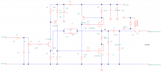
I've just finished drawing up a schematic for my new headphone amp for my Grado SR325is and was wondering whether any discrete amplifier gurus could give me some advice on this circuit. I've built a few headphone amps before and wanted to build something simplistic with feedback and single supply with just one capacitor in the signal path. I'm a little unsure of this design and am almost certain that it could be improved further into quite a decent headphone amp, I've used a couple of ideas I've seen elsewhere for this schematic. I think some of the values could probably be changed (I'm not really keen on making it any more complicated) to improve performance, but lack the experience to know which ones.
. I'm a bit unsure of the gatestopper resistor in the ccs (R23), would the gate to source capacitance of M1 cause it to become unstable?
. Is R24 necessary at such low power levels?
. Would cascoding the JFET on the input with a NPN transitor increase linearity significantly (bearing in mind the open loop gain is only around 10dB)?
I'd be very grateful for any advice!
ephv6.png at Free Image Hosting
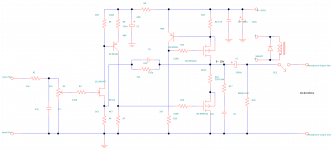
At first sight you seem to have a gain of around 82=8.2k/0.1k from Q2 and almost 10 from Q1.
Are you sure you want such a high gain ?
Also, M2 is biased through R26 from R7. Maybe it would be better to set the bias with a resistor divider on the gate of M2.
Just my 2 cents after a quick look at your schematics, so I might have gotten it wrong.
Are you sure you want such a high gain ?
Also, M2 is biased through R26 from R7. Maybe it would be better to set the bias with a resistor divider on the gate of M2.
Just my 2 cents after a quick look at your schematics, so I might have gotten it wrong.
I was trying to get an open loop gain of around 500 or so to get lots of negative feedback, but if it's going to make the circuit unstable or less linear than it would be with a lower open loop gain, then what values would you suggest? I was also wondering whether it would be better to give more gain to the JFET than Q2?
Also, I'm using the JFETs bias to set the bias voltage for M2, just trying to kill two birds with one stone there, but I know I'm going to have to test individual JFETs as the pinchoff is so variable.
Also, I'm using the JFETs bias to set the bias voltage for M2, just trying to kill two birds with one stone there, but I know I'm going to have to test individual JFETs as the pinchoff is so variable.
I was trying to get an open loop gain of around 500 or so to get lots of negative feedback, but if it's going to make the circuit unstable or less linear than it would be with a lower open loop gain, then what values would you suggest? I was also wondering whether it would be better to give more gain to the JFET than Q2?
Also, I'm using the JFETs bias to set the bias voltage for M2, just trying to kill two birds with one stone there, but I know I'm going to have to test individual JFETs as the pinchoff is so variable.
Very late reply since I haven't visited this site for quite a while.
1. You're right about having a high open loop gain in order to be able to use large amounts of NFB.
Since the schematics is quite simple I thought you were aiming for an open loop design.
2. For biasing, I really think you should use a slightly more complex circuit that delivers a stable bias point, otherwise you might run into a lot of problems.
Btw., any update on this project ? Did you build the circuit ?
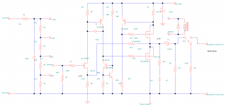
Updates! I built it! (Schematic attached)
Well, I built the circuit a couple of months back, although altered the schematic quite significantly through a bit of reading and some trial and error on a breadboard .
.
I put a constant current source in the voltage amplification stage to bring the open loop gain up really high and also to greatly increase the amp's linearity. I also did away with the emmiter degeneration resistor, it doesn't need it and it actually decreases the amp's linearity. As it is a current feedback amp it doesn't need any kind of frequency compensation and behaves itself very well.
I also used a stepped attenuator instead of a potentiometer on the input as there is a proper volume control on my pre amp unit and I want to be able to adjust if I decide to use headphones that are more or less efficient.
I also increased the value of the output capacitor to increase the damping at lower frequencies and did away with the power supply decoupling cap and resistor as they are not needed.
The biasing also seems to be fairly stable with the JFETs I selected and the overall stability of the amp is excellent, I had to make sure that the cut off for the JFETs was 2.7 volts which meant having to test a lot of FETs. There isn't any drift in the bias at all.
I have it sitting on my desk, it gets a little warm, especially the regulator (LM317) but apart from that it makes a very nice little amp with very clean sound. The THD is less than 0.02% (the lowest my mini oscilloscope/FFT analyzer can detect). It also warms the hands up a treat after coming home on a cold day.
Well, I built the circuit a couple of months back, although altered the schematic quite significantly through a bit of reading and some trial and error on a breadboard
.I put a constant current source in the voltage amplification stage to bring the open loop gain up really high and also to greatly increase the amp's linearity. I also did away with the emmiter degeneration resistor, it doesn't need it and it actually decreases the amp's linearity. As it is a current feedback amp it doesn't need any kind of frequency compensation and behaves itself very well
.I also used a stepped attenuator instead of a potentiometer on the input as there is a proper volume control on my pre amp unit and I want to be able to adjust if I decide to use headphones that are more or less efficient.
I also increased the value of the output capacitor to increase the damping at lower frequencies and did away with the power supply decoupling cap and resistor as they are not needed.
The biasing also seems to be fairly stable with the JFETs I selected and the overall stability of the amp is excellent, I had to make sure that the cut off for the JFETs was 2.7 volts which meant having to test a lot of FETs. There isn't any drift in the bias at all.
I have it sitting on my desk, it gets a little warm, especially the regulator (LM317) but apart from that it makes a very nice little amp with very clean sound. The THD is less than 0.02% (the lowest my mini oscilloscope/FFT analyzer can detect). It also warms the hands up a treat after coming home on a cold day
.Attachments
- Status
- This old topic is closed. If you want to reopen this topic, contact a moderator using the "Report Post" button.
- Home
- Amplifiers
- Headphone Systems
- Simplistic Class A MOSFET Headphone w Feedback: have I got my values right?