There is one with IRF610 here:
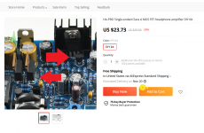
HA-PRO Single-ended Class A MOS FET headphone amplifier DIY Kit | eBay
HA-PRO Single-ended Class A MOS FET headphone amplifier DIY Kit | eBay
Yes, but the picture shows TIP41C written on the PCB. When first released it had IRF610 and then LJM revised with TIP41C.
I assume since the photo was updated to the version with TIP41C that the seller is shipping that version. But I guess it is hard to tell since the picture reads TIP41C and the item title/description says IRF610.
I wonder what else needs to be changed to swap TIP41C with IRF610. Bias but are the changed compatible with the new PCB layout?
As another example this listing has a photo with LM7824 (old old version) with IRF610 written on the board. And it looks like the metal tab IRF610 LJM used. (I think the TIP41 he used was fully plastic encapsulated.)
HA PRO Single ended Class A MOS FET headphone amplifier DIY Kit|Amplifier| - AliExpress
Yet when you read the detailed description you first see a silkscreen outline drawing with LM317 and IRF610 and then you read text that says LM317 and TIP41. So who knows what you get.
I assume you get the latest LM317 TIP41 version. I would like LM317 and IRF610. Of course no published schematics so I will need to do some digging to see if there is any other changes outside of the biasing.
Attachments
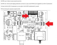
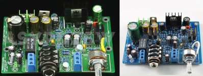
From the attached comparison it looks like the layout and components are the same for the IRF610 and TIP41 versions. Perhaps the BC547 NPN plus emitter resistor "current limiter/regulator" works fine with both the TIP41 and IRF610 to create the constant current sink without any other changes.
Attachments
This week I have been collecting together all of my old HPA projects and dusting them off for a comparison. At the time that I bought or built each one it was highly recommended at the time. (So all were expected to be high performers.) I am just starting this new comparison but so far my original 9 year old HA-PRO (IRF610) is one of my favorites. [Old old original version with different/long PCB. It came with IRF610 and I don't think that version ever shipped with TIP41.] I do not tire of listening to it and I do not find the sound fatiguing. This is similar to what I am experiencing with my Krell KSA50 clone versus various Blameless types.
Any chance that you have a LTSPICE simulation for the HA-PRO (any configuration/version) or the NAIM 42.5? Have you compared the IRF610 version to the TIP41C version? If you did how did they compare in terms of sound signature?
If my (original) HA-PRO is the favorite at the end of the comparison of all my past HPA projects then I would prefer to base a further "best component build" upon the same schematic. If I can only buy and modify the TIP41 version then I could do a side by side comparison with the original long PCB before swapping out the TIP41 for IRF610.
No, I don't have sims and I never tried any version of HA-PRO. I built HA-PRO2 which is opamp based. But, in general, single ended single supply A class amps with current feedback topologies are warm and lush sounding and can be good alternative for headphones listening. In fact, I was hoping that you can share listening impressions about HA-PRO and why you prefer that sound to voltage feedback opamp based topologies.
I always wanted to try it and until your first comment I did not know that there is bipolar version. A few years ago, when I intended to built it, it was available only in MOSFET version.
I always wanted to try it and until your first comment I did not know that there is bipolar version. A few years ago, when I intended to built it, it was available only in MOSFET version.
Frankly, I don't think that TIP 41 can change the sound signature to such degree that you must revert to IRF. In this kind of topology it's not the parts used that make the sound, it's topology itself and I won't be surprised if TIP 41 version sound very similar or better than IRF vession.
I am actually thinking of making myself a spreadsheet of test tracks and observations/comments in an attempt to refine my comparative listening tests between the various HPA. (Such as specific tests of reverbs, delays, stereo imaging, clear definition of multiple harmonies, etc.) I am not sure I want to try to share those specific results (it tends to result in arguments).
I have the HA-PRO2 (and the original long board HA-PRO Class A with IRF610). So far I am preferring the HA-PRO Class A but it is difficult to specifically formulate why. It seems to be coming down to preferring to listen to that for long periods without fatigue. I am not sure how else to put it. I am comparing it against the HA-PRO2 and the TPA6120A2 which are "technically excellent" on paper. But for whatever reason I tire of listening to the HA-PRO2 more quickly (at least so far). Unfortunately I can not correlate to an FFT measurement and an explanation as to why.
If I end up with the TIP41 version of the HA-PRO (which will not be soon) I will try to compare them carefully side by side. I am not sure I want to go to the lengths of placing both inside a chassis with some sort of "blind" switcher. I guess that is important but I am not sure I want to go to such lengths just for personal enjoyment and hobbies. At least with two versions of the HA-PRO (IRF610 and TIP41) the levels would be well matched.
I bought the HA-PRO about nine years ago. About a year ago I bought the HA-PRO2 since the "on paper technical specifications" are excellent. (Pretty much the same as the "on paper technical specifications" of the op-amp used.) The NJM4580 is pretty decent. I might buy OPA1656 to try those in the HA-PRO2. However there are too many reports of people preferring Class A to ignore. I would like to read a more solid explanation and convincing argument regarding the cause of that.
A forum member once asked me about high current NJM4556 opamp used in millions of mass produced CD players and cassette decks for headphone outputs. I once had Yamaha KX530 cassette deck and in that particular deck NJM4556 was used in inverting mode and sounded very well indeed, different than the same chip in non-inverting mode. It seems to me that the non-fatigue sound is due more to the current feedback topology than to A class, but since we are interested here in headphone amps and since we don't need much current, than why not add A class output. When you use opamp in inverting mode, one input transistor is inactive and opamp behaves more like singleton input current feedback amp, hence that non-fatigue sound. You can try any opamp in inverting mode as headphone amp and see if it's singleton input that is non-fatigue. In HA-PRO2 only input opamp is inverting and parallel output opamps are non-inverting. It would be interesting to try that same configuration with parallel output opamps in inverting mode too. That way the whole HA-PRO2 would be in-phase and at the same time it could solve the problem of fatigue and still have great specs.
Frankly, I don't think that TIP 41 can change the sound signature to such degree that you must revert to IRF. In this kind of topology it's not the parts used that make the sound, it's topology itself and I won't be surprised if TIP 41 version sound very similar or better than IRF vession.
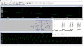
I made a first attempt to simulate the original IRF610 HA-PRO that I have (old long board, IRF610).
Then I looked at photos and board outlines to try to deduce the changes for the TIP41. I found that the new boards are silk screened with a 20 Ohm resistor (for the current sense/regulation) while the old long boards used 10 Ohm (twice the current).
I set the input to 0.1V sine 1 kHz and output load was 40 Ohm to match my ATH-A900. Since both the long board and new HA-PRO have built-in 100 Ohm load resistors and I saw it was having trouble with the 40 Ohm load I replaced the built-in 100 Ohm load with 2000 Ohm in simulation. (The 40 Ohm headphones are already low. I don't know why the design has such a low (100 Ohm) load built-in on the PCB. Hopefully not for... ...stability?)
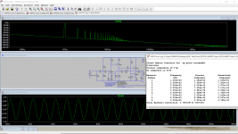
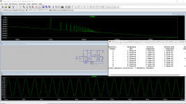
With 1.3V peak output the distortion was about 0.04% THD for the old IRF610 long board and 0.76% THD for the new BJT version. That is just in simulation. I used Bob Cordell's BC550C/BC560C and BD139C models. Later I could try to find a TIP41 model but is that really going to be better than BD139C?
I tried halving the voltage for the BJT case and the results are still very poor at 0.28% THD. I wonder if there is another schematic change (on the TIP41) version that I don't know about. If anyone has a real/verified schematic please let me know. (The new HA-PRO with TIP41.)
Perhaps the modified NAIM design can not drive a large BJT but can drive a MOSFET. Perhaps it can only drive a smaller BJT output and lower currents suitable for line stages?
Perhaps I should not add this but I bet the harmonic profile shown in simulation for the IRF610 sounds better than the harmonic profile shown in the BJT simulation.
Attachments
Last edited:
I made a first attempt to simulate the original IRF610 HA-PRO that I have (old long board, IRF610).
Then I looked at photos and board outlines to try to deduce the changes for the TIP41. I found that the new boards are silk screened with a 20 Ohm resistor (for the current sense/regulation) while the old long boards used 10 Ohm (twice the current).
I set the input to 0.1V sine 1 kHz and output load was 40 Ohm to match my ATH-A900. Since both the long board and new HA-PRO have built-in 100 Ohm load resistors and I saw it was having trouble with the 40 Ohm load I replaced the built-in 100 Ohm load with 2000 Ohm in simulation. (The 40 Ohm headphones are already low. I don't know why the design has such a low (100 Ohm) load built-in on the PCB. Hopefully not for... ...stability?)
With 1.3V peak output the distortion was about 0.04% THD for the old IRF610 long board and 0.76% THD for the new BJT version. That is just in simulation. I used Bob Cordell's BC550C/BC560C and BD139C models. Later I could try to find a TIP41 model but is that really going to be better than BD139C?
I tried halving the voltage for the BJT case and the results are still very poor at 0.28% THD. I wonder if there is another schematic change (on the TIP41) version that I don't know about. If anyone has a real/verified schematic please let me know. (The new HA-PRO with TIP41.)
Perhaps the modified NAIM design can not drive a large BJT but can drive a MOSFET. Perhaps it can only drive a smaller BJT output and lower currents suitable for line stages?
Perhaps I should not add this but I bet the harmonic profile shown in simulation for the IRF610 sounds better than the harmonic profile shown in the BJT simulation.
We should not rely solely on computer software.
Principles in computer software. And physical objects. In fact, there is still a big difference.
MOSFET is used in software simulation. It has no input current factor. This is a problem for software designers.
In practical application, MOSFET needs high VGS. About + - 4V
The impact is serious. We can't output higher voltage.
In practical application. I use ktc4370. TIP41C is not used.
However, both BJTs can get good sound.
Is this site legitimate?We should not rely solely on computer software.
Principles in computer software. And physical objects. In fact, there is still a big difference.
MOSFET is used in software simulation. It has no input current factor. This is a problem for software designers.
In practical application, MOSFET needs high VGS. About + - 4V
The impact is serious. We can't output higher voltage.
In practical application. I use ktc4370. TIP41C is not used.
However, both BJTs can get good sound.
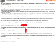
https://www.ilovemyauto.com/Item/14666733067
It states vendor: ljm_ljm2 like your tabao shop.
- Home
- Amplifiers
- Headphone Systems
- HA-PRO2