Relay needs 12V (+/-1V) to be activated. Once activated it will stay activated with lower voltage, say 10V. Relay factory gives the range of over and under voltages the relay will work. Approximately you can expect that 12V relay will work properly from 10-14V, keeping in mind that it needs higher voltage to be activated than to stay activated.
Now that I measured some voltages on the HA-PRO2 I shall explain to you what I think happens. Relay circuit can not work from the regulator output voltage of 12V because there is 3-4V voltage drop in the activating circuit. That way you will have only about 9V for the operation of the relay and it won't work. Therefore it must work from the unregulated DC voltage. If you provide that there is 3-4V more at the input of regulator than at the output regulator, meaning 15-16V, everything should work fine except that relay coil will dissipate somewhat more heat, but it will survive in the long run. You must not have 20V or more at the coil. It will burn the coil.
So I think that the transformer with 2*12 / 2*15 could fit well.
If the real output of 12v is 15.5v
If I buy a transformer of 9v and don’t provide at least 11/11.5v the relay will doesn’t works. Correct?
I’m really confused
These are my options:
Look what I found on AliExpress
30W 30VA Primary Input 0 115 230V SCN Secondary Output 9V 12V 15V 18V 24V R core Transformer Audiophile|Transformers| - AliExpress
Look what I found on AliExpress
Dual 15V 18V 24V 12V 0 12V 15V 0 15V 220V copper custom toroidal isolation transformer 30VA tube power supply 220V to dual 12V|Transformers| - AliExpress
If you look the review, there are some people telling the real output unloaded
Last edited:
You dont need 30VA toroidal transformer for this circuit. An ordinary 6VA EI print transformer is enough. And it's cheap.
HAHN Transformatoren Kern: EI42 nicht kurzschlussfest Leistung: 6VA Eingangsspannung: 230V
BVEI4221223 is your transformer.
HAHN Transformatoren Kern: EI42 nicht kurzschlussfest Leistung: 6VA Eingangsspannung: 230V
BVEI4221223 is your transformer.
HA-PRO2 NEW documentation
I see lots of people on this site and elsewhere looking for the "unobtainium" schematic for the HA-PRO2 headphone amplifier. Before building my own kit, I carefully 'rang out' the PCB foils and made a new schematic in AutoCAD. I also used a caliper to measure the PCB (version 4) and I made a matching PCB Layout drawing in AutoCAD.
I also made quite a few notes on the drawings about suggested parts to buy for outboard components such as the power transformer and RCA input jacks, and I have many notes on the details of the circuit operation, including the heretofore unmentioned part of the circuit that forces the output isolation relay to open whenever there is a DC component on either the Left or Right channels of the amplifier output of more than about 0.8V, either polarity; a useful feature for a totally DC coupled amplifier.
Today (June 2, 2020) I have placed PDF files of both drawings on my own fileshare webpage:
General File Share
I hope people find it useful.
HA-PRO2 documents available
Since the HA-PRO2 does not have documentation available, I have created a full set, downloadable as PDFs from here:
General File Share
Since the HA-PRO2 does not have documentation available, I have created a full set, downloadable as PDFs from here:
General File Share
@micpreampmaker,
Schematic and layout files are great help for users and kit assemblers, and for future reference as service manual in case that something fails. There is one minor change from the board ver.3 which I have. Output resistors were 10R on board ver.3 and are now 2R2 on the board ver.4.
Schematic and layout files are great help for users and kit assemblers, and for future reference as service manual in case that something fails. There is one minor change from the board ver.3 which I have. Output resistors were 10R on board ver.3 and are now 2R2 on the board ver.4.

HA-PRO2 documents available-revised
I have uploaded revised PCB layout and schematic PDFs for the HA-PRO2 (Rev 4) to my file-share webpage:
General File Share
On the PCB Layout, I fixed a couple small cosmetic issues, and changed the op-amp pin designations to match the schematic (one document used 1 & 2 while the other used A & B for the two amps in a given IC, now they both use A & B). On the schematic, I added the missing slashes through the normally closed relay contacts.
HA-PRO2 relay circuit and transformer voltage & power rating
I see a lot of posts here about the correct transformer for the HA-PRO2 amplifier, and about how the relay sub-circuit is powered, and some worrying about the relay voltage. I hope I can help clear some of this up.
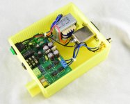
The PCB silkscreen recommends a 24VCT transformer secondary (or dual 12 V secondaries). This is an appropriate secondary voltage for any transformer you are likely to buy, IE/EI or toroid, for this amp. I used a 15VA transformer on mine (roughly 600mA secondary) , which is probably three times what it needs to be. But I wanted to use a toroid, and 15VA was the smallest I could find, at least for an in-stock transformer. Its voltage floats high without load, but under the load presented by this amplifier, if draws down to a reasonable level. I was worried that the voltage regulators would get hot due to dropping the extra voltage, but the input-output voltage difference is only a few volts under load...plenty to assure that the regulator ICs don't stop working, but not so much that they dissipate too much power as heat. On mine, they don't even get noticeably warm.
The relay coil is a nominal 12VDC. This is derived from one side of the secondary, separately from the main rectifier/filter/regulator circuit, and only half wave rectified and barely filtered with a 47uF capacitor. But this is adequate. The relay circuit does not care about power supply ripple, and it draws very little current except briefly when pulling in. And the relay coil is not like an IC you will smoke with too much voltage....it runs without problems on a few extra volts if that is what is supplied. So it is fine with a 24VCT transformer, no worries about relay voltage being too low or too high.
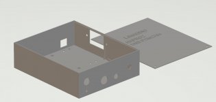
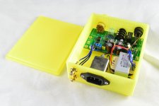
Somebody asked about a good choice for the transformer, and what I selected was a Talema #62052, which is a 15VA dual 12V secondary, and dual 115V primaries, so it can be wired for 115V or 230V mains voltages. It costs only about $10 and is in stock from places like Digikey, etc. Its power rating is overkill, but that does not hurt anything. Its size still fits nicely inside the popular aluminum case kit that many people buy for this HA-PRO2 AMP; nestles between the pins of the IEC power connector and the back edge of the PCB, and still leaves enough room for a fuseholder installed on the back panel OR a fuse holder installed on the bottom of the case.
And if you buy the case kit, the drilled holes on the rear panel are a perfect fit for the popular and readily available Neutrik-Rean # NYS367 series RCA jacks.
I see a lot of posts here about the correct transformer for the HA-PRO2 amplifier, and about how the relay sub-circuit is powered, and some worrying about the relay voltage. I hope I can help clear some of this up.
The PCB silkscreen recommends a 24VCT transformer secondary (or dual 12 V secondaries). This is an appropriate secondary voltage for any transformer you are likely to buy, IE/EI or toroid, for this amp. I used a 15VA transformer on mine (roughly 600mA secondary) , which is probably three times what it needs to be. But I wanted to use a toroid, and 15VA was the smallest I could find, at least for an in-stock transformer. Its voltage floats high without load, but under the load presented by this amplifier, if draws down to a reasonable level. I was worried that the voltage regulators would get hot due to dropping the extra voltage, but the input-output voltage difference is only a few volts under load...plenty to assure that the regulator ICs don't stop working, but not so much that they dissipate too much power as heat. On mine, they don't even get noticeably warm.
The relay coil is a nominal 12VDC. This is derived from one side of the secondary, separately from the main rectifier/filter/regulator circuit, and only half wave rectified and barely filtered with a 47uF capacitor. But this is adequate. The relay circuit does not care about power supply ripple, and it draws very little current except briefly when pulling in. And the relay coil is not like an IC you will smoke with too much voltage....it runs without problems on a few extra volts if that is what is supplied. So it is fine with a 24VCT transformer, no worries about relay voltage being too low or too high.
Somebody asked about a good choice for the transformer, and what I selected was a Talema #62052, which is a 15VA dual 12V secondary, and dual 115V primaries, so it can be wired for 115V or 230V mains voltages. It costs only about $10 and is in stock from places like Digikey, etc. Its power rating is overkill, but that does not hurt anything. Its size still fits nicely inside the popular aluminum case kit that many people buy for this HA-PRO2 AMP; nestles between the pins of the IEC power connector and the back edge of the PCB, and still leaves enough room for a fuseholder installed on the back panel OR a fuse holder installed on the bottom of the case.
And if you buy the case kit, the drilled holes on the rear panel are a perfect fit for the popular and readily available Neutrik-Rean # NYS367 series RCA jacks.
Your point of view is very good.
LJM is your original Class A HAPRO still available with the MOSFET output? I see the LM317 version with TIP41. Is there an LM317 version of the original Class A HAPRO that can use the IRF MOSFET output? (Is the PCB/schematic compatible with MOSFET or only TIP41?)
I have your original original HAPRO with the MOSFET & TL431 power supply. (I am using an external linear power supply to power it with regulated +34VDC.)
I have your original original HAPRO with the MOSFET & TL431 power supply. (I am using an external linear power supply to power it with regulated +34VDC.)
- Home
- Amplifiers
- Headphone Systems
- HA-PRO2