Looks good Carl.
Might want to move the inputs (or have the option) to the other end further away from the AC input. Might not be enough room for the connectors/pots you have chosenjust an idea.
Not enough room to move items on the backside and still fit in the Hammond enclosure. I have used that IO and power scheme before. There is no room but it works well enough.
Attachments
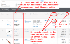
You may contact Jack.I see that Mouser has all the semi's in thru hole.
Does anyone have a pcb for this design?
I was thinking of making one, I will buy the article from LA.
Glad to know that everything is available from Mouser.
Well, I'm ordering parts from Mouser and I'm sort of lost.
I don't have any background in electronics and would love to have some help to select the right part @Mouser.
So, here it goes!
Please let me know I have a lot more to ask
I don't have any background in electronics and would love to have some help to select the right part @Mouser.
So, here it goes!
BTW, is it OK to ask these questions here ?1. 100nF ceramic cap:
Is it regular ceramic vs MLCC ?
Is it a "feed through capacitor" ?
Whats the material of Dielectric ? X7R ?
Voltage rating ?
Radial type, right ?
2. 220uF Electrolytic:
Voltage rating ?
Low ESR, Audio grade ?
Which brand, Panasonic or Nichicon or UCC ?
3. 1N914:
Just a plain jane version or a more exotic one
Is it a "rectifier" or a "switching" type ?
4. Header 1x2:
I'm lost here as there are tonnes of options in Mouser.
Is it a power connector ? What exactly it do ?
5. Header 1x3
Similar questions !
6. Bourns POT 1 (102R):
Not available in Mouser.
7. Bourns POT 1 (201R):
Not available in Mouser.
Please let me know I have a lot more to ask
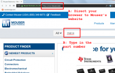
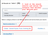
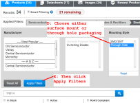
Don't be intimidated, ordering parts from Mouser is not unbearably difficult. Here is the procedure that I myself would use, to order item #3 from your list. Perform the steps in alphabetical order: A, B, C, D, E, F, G, H.
_
_
Attachments
The actual pcb board that will be used should be considered too. The headers, spacing of the electrolytic caps for example will be based on the board you have. Take into account also with the headers the type of connections needed to mate with them. Voltage for any part should be at least 24v. My 220uf are Panasonic fm low esr 63v. The diodes should be normal type. The pot should be bourns, cheaper ones I have used are noisy at times and can go bad/faulty just from light adjustments. Watch out for the output stage resistors (r11,12,13,14,16) they need to be 1 watt rated at least, they can get warm with normal use.
How is every thing going with builds and listening? Are there any new completed build and how does it sound?
THx-Richard
Richard,
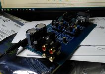
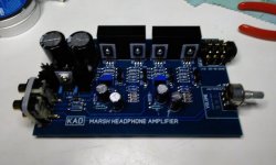
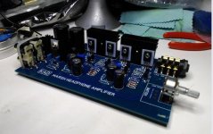
I am only just now completing my build. This is powered by a wallwart and slips into a stock Hammond extruded enclosure.
It is still undergoing tests on my bench but I expect to be listening to it very soon!
Attachments
Last edited:
Beautiful craftsmanship, Carl. Congratulations! Are you using one of those 28-position stepped attenuators called "DACT", as the volume control?
Thanks but I have done nothing special. That's a stock Alps 10K log pot. I like your idea tho.
Once I have convinced myself that I have a worthy implementation of Richard's invention I will most likely swap that pot for an RK27
Parts Express has ALPS RK27s in stock, in many values (unlike Mouser), for about $15. I feel confident that the Parts Express units aren't counterfeit, unlike some of the $8 "ALPS" pots on eBay. When you consider that a nice looking knob runs about $7-15, paying up for the high quality ALPS seems like an easy decision.
Hello Richard and All,
Awhile back I purchased a board and parts kit from jackinj and assembled the Marsh Headphone Amplifier. I recall that it measured 0.006% on the APx 500 analyzer.
Now I am back at it to play with equalization to see what the Harmon Curve sounds like.
I did purchase a shoe box full of transistors and JFET’s to test and match. First I am looking at 2N5457’s and 2N5460’s. If you look at the datasheets notes the tabular data for Idss is measured with a low percentage Pulse and the graphs are plotted with DC. Seems to me the lab test conditions do not have much to with DC operation in an operating circuit. I am learning that these JFET’s take minutes to warmup and settle into stabilized operation. With that being said, just the HVAC blowing cool air over the test causes the source current to fluctuate, just the same as fanning the test jig with a paper plate. Just touching the JFET with a fingertip causes the current to go into the deep.
I am thinking that testing for complementary matched pairs could be better done with individual device testing and placing potential pairs in a real world test circuit
This testing and matching is deeper than I thought. It very well could be done with a $25.00 tester, I do not know. I went all in with a Keysight B2912A Source Measurement Unit and EasyEXPERT software. The software and instrument aren’t on the best of speaking terms just yet. This is a precision calibrated instrument that will measure down to femto-amps, not that it makes any difference.
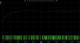
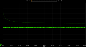
I data logged Idss over minutes for both a 2N5457 (first plot) and 2N5460 (second plot). You can see the current wandering over time. It is like watching slow motion noise. The Idss was least stable over the first short seconds. I am not sure what good for a real world circuit taking a pulse Idss measurement at 0.1 seconds after the pulse is triggered would do. This would not be a very representative measurement, at least in my mind.
See the plots. The currents measured are in the 3mA range, the fluctuation is in the 2nd, 3rd , 4th and 5th digits to the right of the decimal point. Touching or blowing on the JFET caused 0.1’s of mA fluctuation.
In controlled conditions precise measurements are possible.
Thanks DT
Awhile back I purchased a board and parts kit from jackinj and assembled the Marsh Headphone Amplifier. I recall that it measured 0.006% on the APx 500 analyzer.
Now I am back at it to play with equalization to see what the Harmon Curve sounds like.
I did purchase a shoe box full of transistors and JFET’s to test and match. First I am looking at 2N5457’s and 2N5460’s. If you look at the datasheets notes the tabular data for Idss is measured with a low percentage Pulse and the graphs are plotted with DC. Seems to me the lab test conditions do not have much to with DC operation in an operating circuit. I am learning that these JFET’s take minutes to warmup and settle into stabilized operation. With that being said, just the HVAC blowing cool air over the test causes the source current to fluctuate, just the same as fanning the test jig with a paper plate. Just touching the JFET with a fingertip causes the current to go into the deep.
I am thinking that testing for complementary matched pairs could be better done with individual device testing and placing potential pairs in a real world test circuit
This testing and matching is deeper than I thought. It very well could be done with a $25.00 tester, I do not know. I went all in with a Keysight B2912A Source Measurement Unit and EasyEXPERT software. The software and instrument aren’t on the best of speaking terms just yet. This is a precision calibrated instrument that will measure down to femto-amps, not that it makes any difference.
I data logged Idss over minutes for both a 2N5457 (first plot) and 2N5460 (second plot). You can see the current wandering over time. It is like watching slow motion noise. The Idss was least stable over the first short seconds. I am not sure what good for a real world circuit taking a pulse Idss measurement at 0.1 seconds after the pulse is triggered would do. This would not be a very representative measurement, at least in my mind.
See the plots. The currents measured are in the 3mA range, the fluctuation is in the 2nd, 3rd , 4th and 5th digits to the right of the decimal point. Touching or blowing on the JFET caused 0.1’s of mA fluctuation.
In controlled conditions precise measurements are possible.
Thanks DT
Attachments
I experimented with measuring I-V data while the parts were immersed in a circulating water bath. It didn't help much. Perhaps a different, more expensive, nonconductive liquid might do better.
Semiconductor testing often uses big expensive pieces of equipment called "Thermo Stream" , which blow a precisely temperature controlled airflow over the D.U.T. Maybe a ghetto-DIY version would give improved results ...?
_
Semiconductor testing often uses big expensive pieces of equipment called "Thermo Stream" , which blow a precisely temperature controlled airflow over the D.U.T. Maybe a ghetto-DIY version would give improved results ...?
_
Attachments

In Situ Natural Convection soft and gentle draft cooling
Hello,
I am not sure why, people think of gale force wind when they speak of environmentally controlled test conditions. We are not building NASA electronics; there is no need for subtropical or Minnesota in January conditions. I have environmental test chamber stories to tell from my day job.
I believe Carl Huff has it nailed. These parts are being installed on a PCB and placed in an aluminum Hammond enclosure that might sit and operate on my bench top. Sparky’s Lab is typically controlled to 70 degrees by modulating the window opening to let in cool Nor Cal Coast night air.
"In Situ Environmental Testing" is what I call it.
The plots I posted yesterday were done with the French Fry lamp turned on over the bench plus me and my hot breath hovering.
I have a favorite NEMA 1, hinged cover, box to put the test setup in and close the lid. With everything inside and the lid closed the plan is to let Natural Convection provide the soft and gentle cooling draft.
Convective heat transfer - Wikipedia
Thanks DT
Carl Huff, What are the chances of getting 3 or 4 of your PCB's that fit into a aluminum Hammond box?
“In Situ Natural Convection soft and gentle draft cooling” title
Last edited:
See the plots. The currents measured are in the 3mA range, the fluctuation is in the 2nd, 3rd , 4th and 5th digits to the right of the decimal point.
I don't see that on the plots??? In fact I don't see either digits or decimal points?
Would you please encircle these 3rd , 4th , and 5th digits to the right of the decimal point, in some impossible-to-miss bright color on the plots? Probably I have done something very dumb, like fail to expand the image to full size or such like
Hello,
Keysight has at least 3 software packages that operate the B2912A SMU; BenchVue, Quick IV and EasyEXPERT.
What you are looking at is the sort of free 2016 version of BenchVue. I suppose that is why neither X or Y axis is scaled or labeled. I can click on the plot and get either measured current or voltage but not both at the same time. If I save the plot both current and voltage measurements disappear, because the software is free?
Quick IV is also free. I am not spending any time with this software.
I purchased the much more powerful EasyEXPERT to be the primary software. I have been working with Keysight Tech support. Still the required software key is not cooperating. The software reports that the computer Host ID is one thing and my desktop thinks that it is something else. I am taking the instrument to the Keysight Roseville California service center tomorrow.
Meanwhile my plots have no X or Y axis scales or numbers reporting measurement results. Sorry no fun, more fun later.
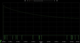
I did place a 2N5457 JFET inside a 8” X 8” X 4” NEMA 1 box on the floor here in my study, The air is calm at 74 degrees, the HVAC has not yet kicked on (not on the Nor Cal Coast today). The Id current vs time plot is much smoother and flatter measured inside the NEMA 1 box with only Natural Convection Cooling inside, much like operating conditions will be.
See the attached plot; at time zero the Id current was 2.10136 mA and at minute 16 the Id settled in at a steady 2.07928 mA.
Voltage is the bottom plot; fluctuating at 20.99999 Volts to 21.0 Volts
Thanks DT
Keysight has at least 3 software packages that operate the B2912A SMU; BenchVue, Quick IV and EasyEXPERT.
What you are looking at is the sort of free 2016 version of BenchVue. I suppose that is why neither X or Y axis is scaled or labeled. I can click on the plot and get either measured current or voltage but not both at the same time. If I save the plot both current and voltage measurements disappear, because the software is free?
Quick IV is also free. I am not spending any time with this software.
I purchased the much more powerful EasyEXPERT to be the primary software. I have been working with Keysight Tech support. Still the required software key is not cooperating. The software reports that the computer Host ID is one thing and my desktop thinks that it is something else. I am taking the instrument to the Keysight Roseville California service center tomorrow.
Meanwhile my plots have no X or Y axis scales or numbers reporting measurement results. Sorry no fun, more fun later.
I did place a 2N5457 JFET inside a 8” X 8” X 4” NEMA 1 box on the floor here in my study, The air is calm at 74 degrees, the HVAC has not yet kicked on (not on the Nor Cal Coast today). The Id current vs time plot is much smoother and flatter measured inside the NEMA 1 box with only Natural Convection Cooling inside, much like operating conditions will be.
See the attached plot; at time zero the Id current was 2.10136 mA and at minute 16 the Id settled in at a steady 2.07928 mA.
Voltage is the bottom plot; fluctuating at 20.99999 Volts to 21.0 Volts
Thanks DT
Attachments
Last edited:
It's regrettable that the two columns of data are not on the same page. Perhaps "Landscape Mode" could fix that?
Here's my two cent analysis of the .pdf data, I hope I have not misinterpreted it
Is that the proper conclusion to draw? Let it stabilize for 15 minutes before trusting the measured number?
Here's my two cent analysis of the .pdf data, I hope I have not misinterpreted it
- Final asymptotic value is 20.80 mA at time=infinity
- Earliest appearance of 20.80 mA is on page #277
- The very last timestep appears on page #201 at t = 51 min 54.5 sec (3114.5 s after 7 o clock)
- Timesteps begin on page #1 at t = 10 min 10.0 sec (700.0 s after 7 o clock)
- Thus 201 pages span 2414.5 seconds, i.e., 12.0 seconds per page
- Measured value == 20.8 mA first appears (277 - 201) = 76 pages from start of experiment, i.e., 912 seconds from start
- Thus the measured value has stabilized at its long term asymptote, 15 minutes + 12 seconds from start
Is that the proper conclusion to draw? Let it stabilize for 15 minutes before trusting the measured number?
I did place a 2N5457 JFET inside a 8” X 8” X 4” NEMA 1 box on the floor here in my study, The air is calm at 74 degrees, the HVAC has not yet kicked on (not on the Nor Cal Coast today). The Id current vs time plot is much smoother and flatter measured inside the NEMA 1 box with only Natural Convection Cooling inside, much like operating conditions will be.
See the attached plot; at time zero the Id current was 2.10136 mA and at minute 16 the Id settled in at a steady 2.07928 mA.
Voltage is the bottom plot; fluctuating at 20.99999 Volts to 21.0 Volts
Thanks DT
Hi,
This is more what to expect - using real world conditions. Inside a closed box with a few holes in top and bottom is all you need for a temp stable interior temp.
I have had my unit on 24/7 for years now and every 6-12 months I check the dc at the output and it is fine or a slight parts drift is brought back to zero again.
Have you tested for dc off set vs temp on a pair .. comp N and P types at same time? By placing my N-P type close to each other is so they see the same temp reduces differential temp differences.
I let my inside box temp raise above room temp -- so room variation has less affect also on the warmer temp inside the box.
All-in-All, quite stable in practice.
Carl .... be sure your wall wort has enough current capacity x 2 channels.
THx-RNMarsh
Last edited:
In practice what would you expect current draw per channel be?Hi,
Carl .... be sure your wall wort has enough current capacity x 2 channels.
THx-RNMarsh
- Home
- Amplifiers
- Headphone Systems
- Marsh headphone amp from Linear Audio