Most of proper headphone measurments published in the internet are done with head and torso simulator and are compensated to match ear hearing curve. So flattening headphones accoring to these measurments actually makes them more linear. However there are lots of diffrent target response curves. Curve developed by Harman is probably is most suitable one for hifi headphone listening. This matter is more precisly explained here.
Over in another thread, Byrtt just showed us how to use the Innerfidelity measurements of specific model headphone responses from a head mannequin and then apply correction via IIR PEQ to achieve the Harman response curve. He did it for a very basic pair of headphones (Status OB-1) running with a SE Class A amp and reports astonishingly good results. When he compared it to the sound of Wesayso's Two Towers - I know that is phenomenal.
More here:
http://www.diyaudio.com/forums/group-buys/302859-xrk971-pocket-class-headamp-gb-92.html#post5127755

Black is target Harman response; Green is response after correction (yellow) is applied; brown is native response. Yes, due to ear canal geometry, the response curves are different but it's useful to take Harman curve as a general first guess.
The corrections were down via DSP in Jriver.
I am heartened that after several years since showing this method and correction , it is catching on faster and faster. There are many curves floating around. I'll read the particulars of this ones measurement technique and how it differs from just making a flat headphone response.
I used a dsp room/speaker correction HDW only becaue I already had it... for proof of concept. Building the dsp and amp inside the headphone somewhere would be great !
-THx- Richard
I used a dsp room/speaker correction HDW only becaue I already had it... for proof of concept. Building the dsp and amp inside the headphone somewhere would be great !
-THx- Richard
https://www.innerfidelity.com/content/sports-car-your-head-audeze-sine-and-cipher-lightning-cable
But then we don't need your amp anymore, just this Cipher Lightning cable.
")
Cheers,
Patrick
But then we don't need your amp anymore, just this Cipher Lightning cable.
Cheers,
Patrick
Like a Sports Car for Your Head: The Audeze SINE and Cipher Lightning Cable | InnerFidelity
But then we don't need your amp anymore, just this Cipher Lightning cable.
Cheers,
Patrick
That is an interesting approach. Distortion wasn't tested. and an octave EQ is a bit too rough.
-Richard
It is all about the curve!
Hello Richard and all,
I went to the shelf to pull down the #3 edition of Linieraudio, the only missing volume was #3. Later I found the missing item in the trunk of my car.
If you notice, the price of graphic equalizers has fallen from the cliff. Recently I purchased a new Klark Teknik DN370 1/3 octave analog equalizer.
Traditionally GE’s are used to tame a room or a stack of speakers and shunned by the golden ears of Hi-Fi. The GE is a toy to me.
Dr. Sean Olive and the crew over at JBL / Harden can equalize a “reference” pair of headphones to be easily confused with a real pair of AKG K701’s or a real pair of Audeze LCD-2’s or any of 4 other well-known headphones. The AES article does not say if an effort was made to equalize any of these headphones to match the Harman (headphone) Target Response Curve.
There was no mention of the brand or model of the “refrence” headphones.
My assumption is that it is all about the curve.
DT
Audio Musings by Sean Olive: A Virtual Headphone Listening Test Method
I am heartened that after several years since showing this method and correction , it is catching on faster and faster. There are many curves floating around. I'll read the particulars of this ones measurement technique and how it differs from just making a flat headphone response.
I used a dsp room/speaker correction HDW only becaue I already had it... for proof of concept. Building the dsp and amp inside the headphone somewhere would be great !
-THx- Richard
Hello Richard and all,
I went to the shelf to pull down the #3 edition of Linieraudio, the only missing volume was #3. Later I found the missing item in the trunk of my car.
If you notice, the price of graphic equalizers has fallen from the cliff. Recently I purchased a new Klark Teknik DN370 1/3 octave analog equalizer.
Traditionally GE’s are used to tame a room or a stack of speakers and shunned by the golden ears of Hi-Fi. The GE is a toy to me.
Dr. Sean Olive and the crew over at JBL / Harden can equalize a “reference” pair of headphones to be easily confused with a real pair of AKG K701’s or a real pair of Audeze LCD-2’s or any of 4 other well-known headphones. The AES article does not say if an effort was made to equalize any of these headphones to match the Harman (headphone) Target Response Curve.
There was no mention of the brand or model of the “refrence” headphones.
My assumption is that it is all about the curve.
DT
Audio Musings by Sean Olive: A Virtual Headphone Listening Test Method
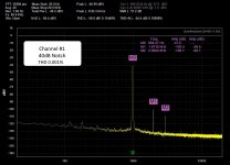
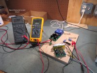
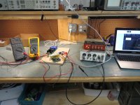
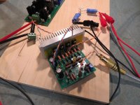
I just finished building and testing both amps. I used Jack's board and his matched devices.
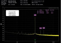
One channel looks very good. The other channel's THD is good but does not match the other. I cannot get the 2nd Harmonic down without compromising the DC offset no matter how much I play with both trim pots.
After 24 hours burn-in the DC Offset remains 1V or less. The heat sink gets mildly warm and is comfortable to touch.
Tomorrow I will start adding proper connectors and a volume pot for some bench listening.
Attachments
Perhaps, you have a mis-matched pair is what I think. better matching will do both-- lower offset and lower 2H. Are you using the same P/N for devices that I used?
What happens to 2H and 3H when you use the dc offset trim pot as I did to zero dc the output? [pot between sources of jFET]
BTW -- -100-110dBv is very good into 68 Ohms.
-Richard
What happens to 2H and 3H when you use the dc offset trim pot as I did to zero dc the output? [pot between sources of jFET]
BTW -- -100-110dBv is very good into 68 Ohms.
-Richard
Last edited:
Hi Richard,
Are gerber or schematics available for the amp?
Thanks
Schematics and parts list and matching instructions are all in the Linear Audio #3 book. I didn't make any extra pcb for others ... but they are available from several people here in this forum.
THx-RNMarsh
What happens to 2H and 3H when you use the dc offset trim pot as I did to zero dc the output? [pot between sources of jFET]
For initial power up I adjusted the dc trim pot midway and the trim pot at R10 for combined resistance of 249ohms to match the value on the positive side. As recommended by you in a past post I adjusted the dc trim pot for lowest THD which left me with about 100mV offset ( 2H less than 3H). Then I adjusted the trim at R10 for lowest offset (close to 0). I went back and forth between the two trim pots for lowest THD and 0 offset. However, every time I trim R10 for lowest offset the THD always increases.
I think there is little need for a trim pot at R10 when using the well matched devices that Jack provided.
BTW -- -100-110dBv is very good into 68 Ohms.
Yes it is! And I think I will leave well enough alone.
Richard,
Is the schematic shown here the full circuit or are there other parts?
Linear Audio | your tech audio resource
You mention matching instructions, do you mean build instructions or transistor matching instructions?
I was hoping Jack still had some kits, but no replies as yet
Is the schematic shown here the full circuit or are there other parts?
Linear Audio | your tech audio resource
You mention matching instructions, do you mean build instructions or transistor matching instructions?
I was hoping Jack still had some kits, but no replies as yet
Richard,
Is the schematic shown here the full circuit or are there other parts?
Linear Audio | your tech audio resource
You mention matching instructions, do you mean build instructions or transistor matching instructions?
I was hoping Jack still had some kits, but no replies as yet
Check your PM..
Richard,
Is the schematic shown here the full circuit or are there other parts?
Linear Audio | your tech audio resource
You mention matching instructions, do you mean build instructions or transistor matching instructions?
I was hoping Jack still had some kits, but no replies as yet[/Q
------------------
What is shown is a X1 buffer. Inside the article is the gain version.
Matching refers to the transistors.
-Richard
In respect of Richard's IP, the boards are still available at $3 per -- these have a slight mod which was suggested quite a while back to incorporate another potentiometer.
Moving the transistors -- the JFETs are matched to about 0.1mA, the bias and output transistors matched for Vbe or hfe -- tricky as temperature.
I use mine with Sennheiser cans which are not a particularly troubling/difficult load.
Moving the transistors -- the JFETs are matched to about 0.1mA, the bias and output transistors matched for Vbe or hfe -- tricky as temperature.
I use mine with Sennheiser cans which are not a particularly troubling/difficult load.
Thanks Richard and Jackinnj,
So the article has schematic, parts list and instructions. Does that mean the PCB has been made by someone else, based on the information in the article?
I've matched BJTs for Vbe before, it can certainly be hours of work so there is definitely a benefit in getting pre-matched parts!
Jackinnj, I also sent you a PM.
Hi All,
Bit of advice pls.
I have finally got round to building the HA and need some advise with psu.
So a bit of advice please on dual rail psu configuration.
Should I
1 use two psu boards fed from one transformer
2 use two boards fed from two transformers
3 use one board and one transformer for board amps
Obviously toroidal dual outputs and all will be fed through the JLH ripple eater from RG
Thanks for the advise
Martin
With mine i used option n°2.
Yes, more expensive, but you'll be rewarded.
If you will use a PS shunt reg( one for channel), you'll be more rewarded.
Of course it depends on what you are aiming for.
I think that this amp deserves the best PS you can/want afford.
Hope this helps.
P.S. I would throw away option 3.
Yes, more expensive, but you'll be rewarded.
If you will use a PS shunt reg( one for channel), you'll be more rewarded.
Of course it depends on what you are aiming for.
I think that this amp deserves the best PS you can/want afford.
Hope this helps.
P.S. I would throw away option 3.
Last edited:
With mine i used option n°2.
Yes, more expensive, but you'll be rewarded.
If you will use a PS shunt reg( one for channel), you'll be more rewarded.
Of course it depends on what you are aiming for.
I think that this amp deserves the best PS you can/want afford.
Hope this helps.
P.S. I would throw away option 3.
Thanks that was my feeling but just wanted to get others advice.
I've plent of spare PSU boards and Shunt Regs so will only need extra transformers
Looking forward to firing it all up soon
Regards
Martin
- Home
- Amplifiers
- Headphone Systems
- Marsh headphone amp from Linear Audio