Agdr, this is all very close to NwAvGuy's own suggestion about building the low power version of the O2 ") :
:
"GAIN STAGE: U1 operates as a non-inverting amplifier for each channel. The crosstalk between the sections is better than –110 dB (I measured it) so there’s no benefit to using single op amps. R16 and R22 were chosen to keep the impedances low to reduce Johnson Noise but not excessively load the amplifier increasing THD. This is one area where things get tricky if you’re “op amp rolling” and testing many op amps in a given circuit. Some low power op amps would work better with higher values for R16 and R22 (and the other 4 gain resistors). For the Low Power version of the O2 using the OPA2277 feedback resistors of 1.5K still work but doubling all the gain resistor values (i.e. ~3K for R16/R22, 2K for R17/R21, etc.) to reduce the load on the low power op amp at the expensive of slightly higher noise. Ideally C19 and C20 should be reduced to 100 pF if R16/R22 are 3K to maintaint roughly the same compensation pole frequency."
One of my O2:s is actually built with the mods he suggests, and your booster board for the output stage!
:"GAIN STAGE: U1 operates as a non-inverting amplifier for each channel. The crosstalk between the sections is better than –110 dB (I measured it) so there’s no benefit to using single op amps. R16 and R22 were chosen to keep the impedances low to reduce Johnson Noise but not excessively load the amplifier increasing THD. This is one area where things get tricky if you’re “op amp rolling” and testing many op amps in a given circuit. Some low power op amps would work better with higher values for R16 and R22 (and the other 4 gain resistors). For the Low Power version of the O2 using the OPA2277 feedback resistors of 1.5K still work but doubling all the gain resistor values (i.e. ~3K for R16/R22, 2K for R17/R21, etc.) to reduce the load on the low power op amp at the expensive of slightly higher noise. Ideally C19 and C20 should be reduced to 100 pF if R16/R22 are 3K to maintaint roughly the same compensation pole frequency."
One of my O2:s is actually built with the mods he suggests, and your booster board for the output stage!
Agdr, this is all very close to NwAvGuy's own suggestion about building the low power version of the O2
Wow!!
I had completely missed that low power chip section in his writings. Thanks for posting! Lol - I came up with nearly the same numbers!
NwAvGuy is still working for us 5 years later. Well this is a great confirmation on those feedback part values.[emoji106]
I feel now the low power version might turn out to somehow be the better and more flexible version, especially rolling opamps. Mine is actually now equipped with lme49900s on adapter and your booster board on opa140s. I don't remember my gain settings, but I think they are set at 1x and 2,5x...
Sounds loud and clear, and objective! [emoji41]
Looking for a suggestion for a mod as I believe I ran into an oscillation issue the other day and it killed one side of my headphones. (RIP Sennheiser CX300II's).
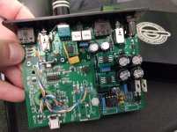
Background - I have a O2amp/DAC combo from JDS Labs running off a wallwart with 1x and 2.5x gains. I have made the following mods to it:
Replaced U1 with a pair of LME49990MA's in a adapter and put 10uf tantalum capacitors across their power supply rails. (this has tightened the highs up quite a bit!)
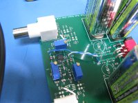
Did the "Your music source feeding the O2 headphone amp is too loud, even with the O2 is the 1x gain position" (I use IEM's and this better suited my listening levels) and "Ground the pot faceplate and shaft to reduce hum and noise pickup" (hey why not) mods from O2 modifications page.
Replaced the wires from the DAC to the AMP with ones I twisted and wrapped then around a ferrite a few times. (killed off some noise I was getting when I turned it up loud - the LME49990MA's are really sensitive!)
Replaced U3/U4 with OPA1688's in adapters. (lows have a good bit more punch now - great mod!)
Now now I believe one of the OPA1688's went into oscillation when I had only one earphone in my ear and a ESD event happened. I live in the cold north and despite my attempts to limit ESD it can still happen and I have been shocked though my ears with different equipment more then once. But this time I started hearing a weird (womp) (womp) noise right after so I killed the power to the amp and afterwards when I powered it back up that side of the earphone is severely degraded. Testing the amp and other earphones shows the amp is fine.
So my question is - what would be the best way of preventing this from happening in the future? (what parts can I throw at it - digikey is only a few clicks away and I like to solder! )
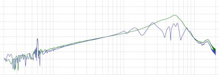
Attached are pics of the amp in its current state and a REW graph of LvsR of the aftermath of the ESD/oscillation event. (blue line of the R side shows how burnt it is)
Background - I have a O2amp/DAC combo from JDS Labs running off a wallwart with 1x and 2.5x gains. I have made the following mods to it:
Replaced U1 with a pair of LME49990MA's in a adapter and put 10uf tantalum capacitors across their power supply rails. (this has tightened the highs up quite a bit!)
Did the "Your music source feeding the O2 headphone amp is too loud, even with the O2 is the 1x gain position" (I use IEM's and this better suited my listening levels) and "Ground the pot faceplate and shaft to reduce hum and noise pickup" (hey why not) mods from O2 modifications page.
Replaced the wires from the DAC to the AMP with ones I twisted and wrapped then around a ferrite a few times. (killed off some noise I was getting when I turned it up loud - the LME49990MA's are really sensitive!)
Replaced U3/U4 with OPA1688's in adapters. (lows have a good bit more punch now - great mod!)
Now now I believe one of the OPA1688's went into oscillation when I had only one earphone in my ear and a ESD event happened. I live in the cold north and despite my attempts to limit ESD it can still happen and I have been shocked though my ears with different equipment more then once. But this time I started hearing a weird (womp) (womp) noise right after so I killed the power to the amp and afterwards when I powered it back up that side of the earphone is severely degraded. Testing the amp and other earphones shows the amp is fine.
So my question is - what would be the best way of preventing this from happening in the future? (what parts can I throw at it - digikey is only a few clicks away and I like to solder!
)Attached are pics of the amp in its current state and a REW graph of LvsR of the aftermath of the ESD/oscillation event. (blue line of the R side shows how burnt it is)
Attachments
Looking for a suggestion for a mod as I believe I ran into an oscillation issue the other day and it killed one side of my headphones. (RIP Sennheiser CX300II's).
Congratulations on your modification efforts!
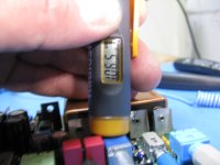
I like your solution on grounding the pot shaft, that wire to the shell of the gain switch. That is going to be more reliable than trying to ground through the shaft nut.Regarding the LME49990 in place of the NJM2068, I don't recommend that one anymore and I've taken it off the websbite. The recent batch of LME49990's - after TI bought National - seem to oscillate in the O2. You can tell if it is oscillating just by putting a finger on it to check temperature. If it oscillates it will run 140F+, too hot to keep a finger on for long, vs. the more normal 100F. Just compare with how hot U2 gets, it should only be slightly hotter.
When I first tried that mod I tried several LME49990s and not oscillations at all. Maybe I just got lucky or maybe there was a process change, but the recent batches I've tried all oscillate. The reason for the oscillation is likely inadequate deocoupling at the power pins for that 110MHz LME49990. NwAvGuy only had the little blue 0.22uF film caps on the rails, which is all the 27MHz NJM2068 needed.
HOWEVER, having said that, you may very well have solved that issue with those tantalum caps you added! So you were right, it probably did sound different because the chip was oscillating, and when you added the tantalum caps on the power rail it either stopped or the oscillation frequency changed. Your LME49990 might be just fine now. If it isn't getting excessively hot now you probably solved it.
The LME49990 oscillation probably isn't the cause of your headphone issue though. It usually oscillates at 11MHz or so. At that frequency the headphone driver coil would be an open circuit.
Regarding the OPA1688 substitution for the NJM4556A chips, there is most likely your problem. That is one of those "try it, you might get lucky" mods that a fellow in one of the other threads came up with. I don't have that one listed here or out on the website. Normally the OPA1688 would require that 47pF compensation capacitor that johnc124 has in the datasheet to increase the phase margin enough to support a wide range of capacitive headphone loads. The O2 PC board just shorts the output to input for unity gain. In the unity gain configuration you would need the capacitor + resistor arrangement from the non-inverting input to ground in unity gain to increase phase margin.
In other words, unless your headphones and headphone cables are a very light capacitive load, there is a very good chance using OPA1688 chips in the O2 will oscillate. I haven't tried adding capacitors on the output to see at what point that happens, but I'll take a guess it isn't much over 100 - 200pF.
But even then I'm not sure that would take out your headphone driver. The most likely thing to do that is DC on the output. Have you checked the DC voltage level on each output of your O2, with nothing plugged into the input jack? It should be around 3mV with the original NJM4556A chips, or 0.5mV with the OPA1688s. If the OPA1688s started oscillating maybe their DC output level went up.
You may very well be right about ESD zapping an OPA1688 too! Static electricity is the #1 killer of chips in my experience, way past soldering iron heat and thermal issues. It could be the OPA1688 is more sensitive to that kind of thing than the older NJM4556A, maybe due to smaller process geometry. From the datasheet the OPA1688 claims to be well ESD protected on the inputs, but I'm not finding anything about the output.
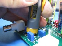
I see another mod to consider, looking at your photo.
The two 2.2uF film caps can be replaced by 3.3uF caps of the same size to drop the lower corner frequency even lower. I think I have that one up on the website. When NwAvGuy designed the O2 those 3.3's were not available yet.do you think soldering a small smd ceramic cap maybe 10uf underneath the .22uf film cap would help?When I first tried that mod I tried several LME49990s and not oscillations at all. Maybe I just got lucky or maybe there was a process change, but the recent batches I've tried all oscillate. The reason for the oscillation is likely inadequate deocoupling at the power pins for that 110MHz LME49990. NwAvGuy only had the little blue 0.22uF film caps on the rails, which is all the 27MHz NJM2068 needed
Congratulations on your modification efforts!
Regarding the LME49990 in place of the NJM2068, I don't recommend that one anymore and I've taken it off the websbite. The recent batch of LME49990's - after TI bought National - seem to oscillate in the O2. You can tell if it is oscillating just by putting a finger on it to check temperature. If it oscillates it will run 140F+, too hot to keep a finger on for long, vs. the more normal 100F. Just compare with how hot U2 gets, it should only be slightly hotter.
When I first tried that mod I tried several LME49990s and not oscillations at all. Maybe I just got lucky or maybe there was a process change, but the recent batches I've tried all oscillate. The reason for the oscillation is likely inadequate deocoupling at the power pins for that 110MHz LME49990. NwAvGuy only had the little blue 0.22uF film caps on the rails, which is all the 27MHz NJM2068 needed.
HOWEVER, having said that, you may very well have solved that issue with those tantalum caps you added! So you were right, it probably did sound different because the chip was oscillating, and when you added the tantalum caps on the power rail it either stopped or the oscillation frequency changed. Your LME49990 might be just fine now. If it isn't getting excessively hot now you probably solved it.
The LME49990 oscillation probably isn't the cause of your headphone issue though. It usually oscillates at 11MHz or so. At that frequency the headphone driver coil would be an open circuit.
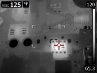
Just checked the LME49990's and it does not look like they are happy so I popped the stock 2068 back in for now. See the attached FLIR image. So my 10uf tantalum capacitors across their power supply rails does not seem to have done anything. (no loss as I just scavenged them from other scrap gear.) But if you have other suggestions I am open to playing around with it! (Even at 150F they sounded not bad to me - but that does seem a bit toasty.)
Regarding the OPA1688 substitution for the NJM4556A chips, there is most likely your problem. That is one of those "try it, you might get lucky" mods that a fellow in one of the other threads came up with. I don't have that one listed here or out on the website. Normally the OPA1688 would require that 47pF compensation capacitor that johnc124 has in the datasheet to increase the phase margin enough to support a wide range of capacitive headphone loads. The O2 PC board just shorts the output to input for unity gain. In the unity gain configuration you would need the capacitor + resistor arrangement from the non-inverting input to ground in unity gain to increase phase margin.
In other words, unless your headphones and headphone cables are a very light capacitive load, there is a very good chance using OPA1688 chips in the O2 will oscillate. I haven't tried adding capacitors on the output to see at what point that happens, but I'll take a guess it isn't much over 100 - 200pF.
But even then I'm not sure that would take out your headphone driver. The most likely thing to do that is DC on the output. Have you checked the DC voltage level on each output of your O2, with nothing plugged into the input jack? It should be around 3mV with the original NJM4556A chips, or 0.5mV with the OPA1688s. If the OPA1688s started oscillating maybe their DC output level went up.
Checked the voltage across the jack with nothing plugged in - and my meter is reading 0.3mv on one side and 0.2mv on the other with the 1688's. Popping the 4556's back in gives me 3.8mv and 3.6mv. So unless I am measuring incorrectly they seem even better then you were expecting. I would not mind hearing more about this "in the unity gain configuration you would need the capacitor + resistor arrangement from the non-inverting input to ground in unity gain to increase phase margin." you spoke of.
You may very well be right about ESD zapping an OPA1688 too! Static electricity is the #1 killer of chips in my experience, way past soldering iron heat and thermal issues. It could be the OPA1688 is more sensitive to that kind of thing than the older NJM4556A, maybe due to smaller process geometry. From the datasheet the OPA1688 claims to be well ESD protected on the inputs, but I'm not finding anything about the output.
Nothing seems to have died in the amp rather - it looks like the ESD managed to push something so far out of bounds that it started to oscillate. I have had the 1688's in there for at least a month or more with daily use and this is the first time that happened. As I think of it - the ESD could of just directly killed the driver as well and the amp oscillating could of just been a side effect. But I figure if I can do something stop it from happening - why not! (gave me quite a startle - ZAP ow (WOMP WOMP WOMP) WT#$@$?!?
I see another mod to consider, looking at your photo.
Your referring to C13 and C14 correct? Something like R463R433040M2K KEMET | Capacitors | DigiKey or C4ATHBW4330A3GJ KEMET | Capacitors | DigiKey is what your thinking of?
OrBy - yep 150 degrees F is oscillating! I agree, the LME49990 does sound good (still) even oscillating. I can't really tell just from listening if the chip is oscillating or not.
The NJM2068 really is a pretty good chip. My suggestion would be just to leave it, or if you wanted to try another chip (I haven't tested this one myself) the OPA1612 is bipolar and very low THD+N (also SMD and would need an adapter, but it is a dual like the NJM2068 so just a single-sided dual adaptor). The OPA1612 is still unity gain stable and "only" 40MHz GBW, so possibly less of an oscillation problem. If you should try the OPA1612 please post your results!
The output chips in the O2 are ones that need a root canal, so to speak. For that my Booster Board DIY project here is a better solution than the OPA1688. That board is a OPA827 wrapped around a LME49600 on each channel. Much more current capability for peaks, no problem driving normal capacitive headphone loads, and a headphone relay to eliminate thumps.
Which reminds me, someone installing a booster board just ran into an issue. Only 12Vac should be used with the O2, nothing higher, due to NwAvGuy not having the voltage regulators heat sinked. I believe JDS ships theirs with 12Vac and that is what I recommend too. A fellow happened to be using and 18Vac wall transformer. With the current capability of the booster board that is enough to fry the O2 regulators if a headphone is using more than 10mA per channel or so. No problem though if using a 12Vac transformer. A person can get away with more than 12Vac like this *if* they are sure all their headphones or IEMs are very sensitive and don't pull more than 10mA or so per channel.
I have a pile of headphone SPL charts here which show required voltage swing and current (both rms) to hit 90dB SPL and 110dB SPL for many different headphones:
https://drive.google.com/drive/folders/0B67cJELZW-i8eFVrX2taU25LUWs?usp=sharing
Johnc124 clued me in about the offset voltages on the OPA1688. Apparently he wrote or edited the datasheet at TI. The sheet shows 250uV for typical input offset, but in 1x voltage gain mode I was seeing a lot of 500uV and even a few 650uV+ in actual practice. He says it is statistical, if I understood that correctly. The 250uV in the datasheet "typical" column is 1 sigma out, 500uV is 2 sigmas, etc. I've seen enough 500uV offsets now that I'm quoting 500 these days to be on the conservative side. But on the other hand I've seen a bunch of 150uV or less too.
Another thing from that chat, just because the two sides of the dual op-amp are on the same piece of silicon there really isn't an expectation of matching of offsets on the two channels. The OPA1688 DC offsets that I've seen so far are typically not a close match between channels. Take a look at my last couple of posts in the ODA thread here. I tested 20 NJM4556A "SIP" inline chips for offset for a fellow building an ODA. Not much match at all between the two halves of each dual chip. But that is perfectly OK given how low these offset numbers are for the OPA1688! But with the OPA827 wrapped around a LME49600 buffer (Booster Board), the maximum DC offset on either channel is usually no more than 50uV to 100uV. Fantastic chip. It doesn't have the current output capability of the OPA1688 though, hence looping it around the LME49600.
For setting the OPA1688 up in unity gain take a look at the Super CMOY single-chip V4.1 schematic here:
https://drive.google.com/drive/folders/0B67cJELZW-i8Vi1pcFc1aVpCdHM?usp=sharing
So for example on the right channel, for 1x voltage gain, R9, R11, and C13 are installed while the 47pF C7 is omitted. For 2x and higher voltage gain C13 is ommited, C7 is installed, and the end of R9 that used to go to C13 is now grounded with a jumper. Then same matching thing happens on the left channel, of course. Given all there required parts there is just no way (that I can see anyway) to get them on the O2 PCB. He had the output of each NJM4556A chip half tied back to the inverting input. All four of those PCB traces would have to be cut and part(s) inserted, plus more part(s) from inverting input to ground that don't currently exist.
Hey you could be right about the ESD, maybe it directly killed the driver! For a very sensitive headphone or IEM maybe that could happen with a big enough spark.
The capacitor you want is a 505-MKS23.3/63/5 polyester film for $3 each. An added benefit is they are 5% for even better channel matching. The 2.2uF the NwAvGuy has in the BOM is also polyester. Unfortunately the polypropylene are too big to fit. I had forgotten that Digikey doesn't stock WIMA and Kemet doesn't seem to have anything appropriate. So this one is a Mouser-only part.
The NJM2068 really is a pretty good chip. My suggestion would be just to leave it, or if you wanted to try another chip (I haven't tested this one myself) the OPA1612 is bipolar and very low THD+N (also SMD and would need an adapter, but it is a dual like the NJM2068 so just a single-sided dual adaptor). The OPA1612 is still unity gain stable and "only" 40MHz GBW, so possibly less of an oscillation problem. If you should try the OPA1612 please post your results!
The output chips in the O2 are ones that need a root canal, so to speak.
For that my Booster Board DIY project here is a better solution than the OPA1688. That board is a OPA827 wrapped around a LME49600 on each channel. Much more current capability for peaks, no problem driving normal capacitive headphone loads, and a headphone relay to eliminate thumps.Which reminds me, someone installing a booster board just ran into an issue. Only 12Vac should be used with the O2, nothing higher, due to NwAvGuy not having the voltage regulators heat sinked. I believe JDS ships theirs with 12Vac and that is what I recommend too. A fellow happened to be using and 18Vac wall transformer. With the current capability of the booster board that is enough to fry the O2 regulators if a headphone is using more than 10mA per channel or so. No problem though if using a 12Vac transformer. A person can get away with more than 12Vac like this *if* they are sure all their headphones or IEMs are very sensitive and don't pull more than 10mA or so per channel.
I have a pile of headphone SPL charts here which show required voltage swing and current (both rms) to hit 90dB SPL and 110dB SPL for many different headphones:
https://drive.google.com/drive/folders/0B67cJELZW-i8eFVrX2taU25LUWs?usp=sharing
Johnc124 clued me in about the offset voltages on the OPA1688. Apparently he wrote or edited the datasheet at TI. The sheet shows 250uV for typical input offset, but in 1x voltage gain mode I was seeing a lot of 500uV and even a few 650uV+ in actual practice. He says it is statistical, if I understood that correctly. The 250uV in the datasheet "typical" column is 1 sigma out, 500uV is 2 sigmas, etc. I've seen enough 500uV offsets now that I'm quoting 500 these days to be on the conservative side.
But on the other hand I've seen a bunch of 150uV or less too. Another thing from that chat, just because the two sides of the dual op-amp are on the same piece of silicon there really isn't an expectation of matching of offsets on the two channels. The OPA1688 DC offsets that I've seen so far are typically not a close match between channels. Take a look at my last couple of posts in the ODA thread here. I tested 20 NJM4556A "SIP" inline chips for offset for a fellow building an ODA. Not much match at all between the two halves of each dual chip. But that is perfectly OK given how low these offset numbers are for the OPA1688! But with the OPA827 wrapped around a LME49600 buffer (Booster Board), the maximum DC offset on either channel is usually no more than 50uV to 100uV. Fantastic chip. It doesn't have the current output capability of the OPA1688 though, hence looping it around the LME49600.
For setting the OPA1688 up in unity gain take a look at the Super CMOY single-chip V4.1 schematic here:
https://drive.google.com/drive/folders/0B67cJELZW-i8Vi1pcFc1aVpCdHM?usp=sharing
So for example on the right channel, for 1x voltage gain, R9, R11, and C13 are installed while the 47pF C7 is omitted. For 2x and higher voltage gain C13 is ommited, C7 is installed, and the end of R9 that used to go to C13 is now grounded with a jumper. Then same matching thing happens on the left channel, of course. Given all there required parts there is just no way (that I can see anyway) to get them on the O2 PCB. He had the output of each NJM4556A chip half tied back to the inverting input. All four of those PCB traces would have to be cut and part(s) inserted, plus more part(s) from inverting input to ground that don't currently exist.
Hey you could be right about the ESD, maybe it directly killed the driver! For a very sensitive headphone or IEM maybe that could happen with a big enough spark.
The capacitor you want is a 505-MKS23.3/63/5 polyester film for $3 each. An added benefit is they are 5% for even better channel matching.
The 2.2uF the NwAvGuy has in the BOM is also polyester. Unfortunately the polypropylene are too big to fit. I had forgotten that Digikey doesn't stock WIMA and Kemet doesn't seem to have anything appropriate. So this one is a Mouser-only part.
Last edited:
I may give the OPA1612 a try - figure I could put in a little order for the caps and grab one of them as well. Looks like they have 3 parts:
http://ca.mouser.com/ProductDetail/...=sGAEpiMZZMtxdzBvM0rKcSBSa86la16FldxaoyTC43k=
http://ca.mouser.com/ProductDetail/...GAEpiMZZMtxdzBvM0rKcT%2bJ7SlI7crb5i5hLtG5v4A=
http://ca.mouser.com/ProductDetail/...=sGAEpiMZZMtxdzBvM0rKcSBSa86la16Fc0OGuY6L6Lo=
Any suggestion as to witch version?
LOL - never fails - does not look like mouser carries any adapter boards currently.
The OPA1612 doesn't work as a NJM2068 replacement in the O2
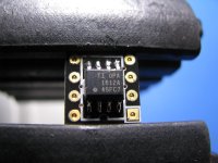
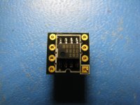
I had forgotten that I bought a bunch of these Brown Dog SOIC-8 to DIP 8 adapters recently:
SO8 to DIP8 Adapter | Cimarron Technology, Inc.
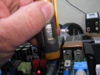
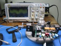
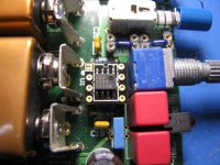
They are small enough to fit in that physical space around the NJM2068 area in the O2. I just soldered up a OPA1612 on one and gave it a try, but... it oscillates. 110F measuring the temperature (the 105F in the photo wasn't the max). I don't see the oscillation on the scope though, at the pot feed. The 1mV of background EMI shown in the photo is the same thing exactly that I get with the NJM2068. The chip sounds just fine listening to the O2 too. It must be internal oscillation due to decoupling problems. The NJM2068 runs at only 87F.
If anyone wants to mess with this themselves, I see that Brown Dog even optionally offers an OPA1612 soldered up on the adapter, in that drop-down list on the page, for $14 more. You would want the OPA1612AID version to solder it yourself.
I'm back to not having any alternative "upgrade" recommendations for the NJM2068 in the O2, unfortunately.
LOL - never fails - does not look like mouser carries any adapter boards currently.
I had forgotten that I bought a bunch of these Brown Dog SOIC-8 to DIP 8 adapters recently:
SO8 to DIP8 Adapter | Cimarron Technology, Inc.
They are small enough to fit in that physical space around the NJM2068 area in the O2. I just soldered up a OPA1612 on one and gave it a try, but... it oscillates. 110F measuring the temperature (the 105F in the photo wasn't the max). I don't see the oscillation on the scope though, at the pot feed. The 1mV of background EMI shown in the photo is the same thing exactly that I get with the NJM2068. The chip sounds just fine listening to the O2 too. It must be internal oscillation due to decoupling problems. The NJM2068 runs at only 87F.
If anyone wants to mess with this themselves, I see that Brown Dog even optionally offers an OPA1612 soldered up on the adapter, in that drop-down list on the page, for $14 more. You would want the OPA1612AID version to solder it yourself.
I'm back to not having any alternative "upgrade" recommendations for the NJM2068 in the O2, unfortunately.
Attachments
Last edited:
I had forgotten that I bought a bunch of these Brown Dog SOIC-8 to DIP 8 adapters recently:
SO8 to DIP8 Adapter | Cimarron Technology, Inc.
They are small enough to fit in that physical space around the NJM2068 area in the O2. I just soldered up a OPA1612 on one and gave it a try, but... it oscillates. 110F measuring the temperature (the 105F in the photo wasn't the max). I don't see the oscillation on the scope though, at the pot feed. The 1mV of background EMI shown in the photo is the same thing exactly that I get with the NJM2068. The chip sounds just fine listening to the O2 too. It must be internal oscillation due to decoupling problems. The NJM2068 runs at only 87F.
If anyone wants to mess with this themselves, I see that Brown Dog even optionally offers an OPA1612 soldered up on the adapter, in that drop-down list on the page, for $14 more. You would want the OPA1612AID version to solder it yourself.
I'm back to not having any alternative "upgrade" recommendations for the NJM2068 in the O2, unfortunately.
Well thanks for saving me the trouble of ordering/testing myself! Ill still likely grab a few of the caps you have suggested but I may hold off till I have a few more things to add to the order. Kinda torn with what to do at this point. Going to likely leave the 1688's in cause they do sound better to me then the 4556's but I fry another set of buds it may be worth going all out and picking up a booster board. (my A/C adapter is a 12v 200ma one so it should be safe)
I'm back to not having any alternative "upgrade" recommendations for the NJM2068 in the O2, unfortunately.
What about the LM4562 or the OPA2227?
Although maybe not really "upgrades" according to NwAvGuys own measurements, but the OPA did seem to outperform the NJM2608 slightly in terms of residual noise. But then again, not really worth the cost I guess.
I too did get one of these adapters with the lme49990s, from the same eBay seller as you. They really got hot, at over 75 °C...
It would be interesting to see some results with JRCs MUSES opamps in there too. If I send you a 8820 I have laying around, could you do some measurements?
Hi, sorry about the delayed reply.
I agree, the LM4562/LME49710 (same chip) & OPA2227 should work, although it might be a small downgrade, given NwAvGuy's testing comments. Hey *very* good thoughts about the muses 8820! I had forgotten about that. It is the "offical" upgrade from NJM. No need to send one, I'm pretty sure I have one that has been sitting here for the better part of a year. I'll solder it on an adaptor and let's see what happens. This might turn into a fantastic upgrade. Great suggestion!
Just a quick summary on the muses chips (at Mouser) for anyone else reading this. NJM created this muses series a couple of years ago as their high end audio chips. The first ones were the muses01 (jfet) and muses02 (bipolar) in DIP8 packages that go for the rather breathtaking price of $46 each, with almost zero technical justification for the cost in the datasheet. Then they came out with what they describe as their "mass market" version of the muses (the 01 and 02 are supposed to be hand-trimmed during production according to some marketing material), the muses8820 (bipolar) and muses8920 (jfet) for a more reasonable $10 & $12. So if someone wanted to drop some serious money into their O2 as a test it would also be possible just to plug in a muses02 in place of the NJM2068. But again it may oscillate and you would be out $50.
At $10 the muses 8820 is worth the test. The GBP of these chips are even less than the NJM2068, around 10MHz for the bipolar, so there should be a very good chance they won't oscillate in the O2.
Last edited:
No worries!
I got the DIP8 version of the 8820 and tried it in different diy-projects I have, among them, a riaa-preamp and my O2:s (with booster boards!) and it didn't get warmer than finger-warm, where the LME49990s on adapter would get boiling hot. So I guess it's doing fine. But I don't have the means (nor the knowledge) to do measurements.
In the end, I am back to using the 2068 in my desktop O2, and the OPA2277 in the battery powered low power version (both with booster board!).
Another thing that I am wondering about is whether or not it would be possible to use Li-Ion 9v batteries instead of the Ni-MH ones. I read somewhere that the ones that have a protection circuit should accept a charge as long as it is voltage constant, which, if I understand correctly, it is in the O2's charging circuit. Is that even remotely right?... Sorry if it is a dumb question!
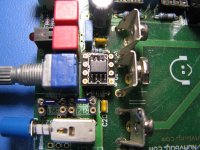
Chiroshi - the muses8820 works! Photos below.
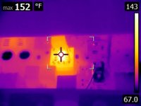
Based on these results I'm going to revise my opinion about the OPA1612, I think it was working just fine too. Apparently 110F is OK, given the 1.5K load on both halves of the chip (the O2's feedback resistor). 40F less than the NJM49990 was running at! I don't see any oscillation on the scope, even when I probe right at the pins on the chip. Same was true with the OPA1612. I'm guessing the larger DIP8 package is dissipating heat better hence the lower package temperature for the NJM2068. I'll find some package thermal resistance numbers on a datasheet somewhere and verify. I see that the quiescent current in both the muses8820 and OPA1612 (x2 datasheet number to get both chip halves) is about 40% more than the NJM2068. That can account for some additional chip heating.
Photos:
* 4832 is the muses8820 soldered onto the adapter and 4833 is the adapter installed in an O2.
* 4334 is the 8820's temperature reading. The highest I measured was 107F, very similar to the 110F for the OPA1612 but miles away from the 150F for the LME49990.
* The final two are an OPA1612 soldered into a another project of mine, a Hall notch filter with much better decoupling, just as another data point on temperatures. The notch filter has a 0.1uF and 4.7uF X7R 0805-sized SMD ceramic on each power rail, with a solid ground plane on the board. Yet the temperature reading here is in the ballpark of the O2 readings at 103.5F. Especially given the much lighter load (around 7K) on the notch filter than the O2's 1.5K. The notch board is running at +/-16.4Vdc though vs. the +/-9.2Vdc in the O2. At this point I think those 100F-or-so O2 readings must be perfectly normal, no oscillation.
The muses8820 sounds great, as did the OPA1612! Both are viable "upgrade" chips to try in place of the NJM2068.
Photos below.Based on these results I'm going to revise my opinion about the OPA1612, I think it was working just fine too. Apparently 110F is OK, given the 1.5K load on both halves of the chip (the O2's feedback resistor). 40F less than the NJM49990 was running at! I don't see any oscillation on the scope, even when I probe right at the pins on the chip. Same was true with the OPA1612. I'm guessing the larger DIP8 package is dissipating heat better hence the lower package temperature for the NJM2068. I'll find some package thermal resistance numbers on a datasheet somewhere and verify. I see that the quiescent current in both the muses8820 and OPA1612 (x2 datasheet number to get both chip halves) is about 40% more than the NJM2068. That can account for some additional chip heating.
Photos:
* 4832 is the muses8820 soldered onto the adapter and 4833 is the adapter installed in an O2.
* 4334 is the 8820's temperature reading. The highest I measured was 107F, very similar to the 110F for the OPA1612 but miles away from the 150F for the LME49990.
* The final two are an OPA1612 soldered into a another project of mine, a Hall notch filter with much better decoupling, just as another data point on temperatures. The notch filter has a 0.1uF and 4.7uF X7R 0805-sized SMD ceramic on each power rail, with a solid ground plane on the board. Yet the temperature reading here is in the ballpark of the O2 readings at 103.5F. Especially given the much lighter load (around 7K) on the notch filter than the O2's 1.5K. The notch board is running at +/-16.4Vdc though vs. the +/-9.2Vdc in the O2. At this point I think those 100F-or-so O2 readings must be perfectly normal, no oscillation.
The muses8820 sounds great, as did the OPA1612! Both are viable "upgrade" chips to try in place of the NJM2068.
Attachments
Last edited:
Chiroshi - the muses8820 works!
The muses8820 sounds great, as did the OPA1612! Both are viable "upgrade" chips to try in place of the NJM2068.
Good stuff! 110F is about 43 Celsius, which confirms my finger's temp measurement! [emoji2]
Skickat från min Nexus 5X via Tapatalk
The muses8820 sounds great, as did the OPA1612! Both are viable "upgrade" chips to try in place of the NJM2068.
Parts finally came in - I soldered up a 1612 and swapped out the 2068.
Sounds good but it def does seem a bit toasty.
125F-130F where the 49990's were 150F-155F.
Wondering if I should of grabbed a muse while I was at it...
Attachments
O2 C2-C5 substitute for low ESR *and* now temperature
I have been building up a couple of O2 PC boards using NwAvGuy's original BOM parts list and just noticed something. Years ago I posted a substitution suggestion for the filter capacitors, C2 - C5, to use a low ESR capacitor. It is even one of the alternates that NwAvGuy listed in his BOM for these caps, the Panasonic EEU-FR1V471B (or without the B, EEU-FR1V471, the B is reel tape and without is bulk, either is OK), Mouser #667-EEU-FR1V471B or 667-EEU-FR1V471, or Digikey P14441-ND. The "standard" BOM capacitor has a ripple current of 555mA (when de-rated for 60Hz) vs. this capacitor with 1168mA at 60Hz (and just 28 milli-ohms of ESR).
The new capacitor here also has a higher temperature rating of 105C and longer life of 8,000 hours, vs. just 85C and 3,000 hours for the "standard" capacitor. This seemed like just some longer life and better reliability until now. But I just noticed that C5 is right next the voltage regulators (U5 & U6) in the O2, close enough to get extremely hot via thermal radiation. The O2 voltage regulators can get very hot - 150F to over 180F - due to not having heat sinks. Higher transformer voltages, more than 12Vac, and/or low impedance loads, especially cause higher vreg temperatures.
A couple of folks have actually posted in the O2 thread over the years about how hot their C5 is getting so it isn't just theoretical. From thermal conduction through traces and direct radiation (C5 nearly touches U5 and U6). So there really is a good reason to use a higher temperature-rated capacitor for the filters in the O2! C5,will likely have a shorter life than the rest due to proximity to the vregs.
Last edited:
- Status
- This old topic is closed. If you want to reopen this topic, contact a moderator using the "Report Post" button.
- Home
- Amplifiers
- Headphone Systems
- O2 amp CRC, diode, cap, and heatsink mods