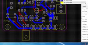
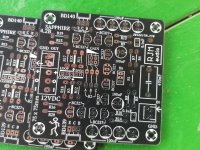
Looks good - I think. If it was me I would add a couple more caps in the extra board space.
Something like that? It's a quick sketch ...
Attachments

..for those, who do.
Hello
How to open these files?
it is possible to import into Eagle?
THX
Last edited:
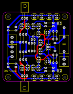
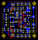
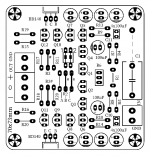
..those are Gerber-Files, you can drop the *.zip-file to your PCB-Supplier, for example: Online Gerber Viewer - PCB Prototype the Easy Way - PCBWay


(you've attached the current version of the Sapphire BOM, as available from my web site)
Yes, of course, you can use the default parts. You have multiple choices, one of them is to build with the default parts list.
I do recommend you spend a little time to at least recognize the available options however.
There are essentially three, (default setting in parenthesis)
The feedback connection (open loop)
The gain settings (8-15-25 dB)
The bias current (37 mA)
If you want open loop (no global feedback) and have no particular drive concerns, the defaults will be fine.
If you prefer closed loop, the values of R2A,B,C change, in addition to R3/R3X, because different resistances are needed to maintain the same 8-15-25 dB gain as before.
Finally, you can adjust the gain setting to something other than 8-15-25 dB if you have any special requirements (like using the Sapphire as a line preamp for example).
Sapphire Blues
I am not sure what to do next to solve my Sapphire assembly problem, which was initially high DC offset voltage on the output.
I assembled a single board (version 4.2b) using the resistor values shown on the drawing (and BOM) for the version 4.1z board. I chose closed loop gain and installed R3X at 2210 ohms and R2A as 680 ohms with R3, R2B and R2C empty.
I checked the transistors prior to installation and found (Ebay cheap meter) that the BC 337 population had an hFe frequently indicating 500 plus. The BC 327s were 430-440 typical. I installed an hFe of 446 for Q1 and Q2 had an hFe of 481. All resistor values were checked before installing also.
PS input was pre-regulated to about 18.7 volts per side. Powering it up, the board regulated voltages were within 15 mv of each other at about 11.1 volts. With the signal input shorted, the DC offset was initially about -3.5 volts. Adjusting R6 (initially midrange of 5K) allowed maybe 1/2 volt change in the offset. R6 does function correctly. I re-checked transistor placements, resistors and solder joints but found no screw-ups.
I connected some old headphones and an audio source and it played undistorted.
I then did a search and found a discussion (post 1079 from February 2017, not sure what PCB version) where the resolution for a large offset was to increase R4 or R5 a few thousand ohms.
With that thought and some experimentation (and more must be better) I was able to get nominal zero offset, with R6 in mid position, by increasing R5 to 118.5K ohms while maintaining R4 at the standard 100K. The drift was maybe up to 20 mv over time except I noticed voltage offset would change by 100 mv or more by exhaling onto the board. (I was not wearing a face mask but I am maintaining a 6 foot distance from the un-built PCB).
However, with DC offset problem “fixed” the board now passes no signal. Restoring R4 to the original 100K (offset back to about -3.5v) did not make it play music again either.
What did I foul up? I don’t want to build a second board until I make the first one work. Thanks in advance for any help.
For troubleshooting I'd recommend switching it back to an open loop configuration. It makes things a little bit easier.
Knowing the power supply gives the proper voltages is reassuring. Having about 1 V of adjustment range in R6 also seems about right.
A large offset, following by a nonfunctioning circuit, strongly suggests a transistor has failed.
If you find a transistor is placed incorrectly (wrong type or wrong orientation) it's a simple matter to fix. If the transistors are all correct but one has physically failed, it's hard to pin down which one.
@wolkegeist
Yes, for the Sapphire 3 the input (op amp) stage and output (transistor) stage are independent so the output can be replaced with whatever you want.
The only conditions are that the op amp be capable of driving the output stage, and the power supply be capable of feeding it.
Yes, for the Sapphire 3 the input (op amp) stage and output (transistor) stage are independent so the output can be replaced with whatever you want.
The only conditions are that the op amp be capable of driving the output stage, and the power supply be capable of feeding it.
- Home
- Amplifiers
- Headphone Systems
- RJM Audio Sapphire Desktop Headphone Amplifier