I've been using the VPM series equivalent of the transformer in the BOM for a while (wired the same way as Richard's open chassis on the website).
I've just re-read the data sheet and noticed that there are only instructions for a single 12V or 24V output.
It also states:
"Primary and secondary windings are designed to be connected in series or parallel. Windings are not intended to be used independently."
Any idea's why they would write that or if the transformers are not intended to be used with dual 12V outputs?
The short answer is there's no problem when wired as I have it with the DBRB. I did actually check with Triad on that.
"independently" includes all kinds of strange use cases which would fall out of the performance envelope. Like running one winding with more current than the other, or widely different floating potentials. So to cover themselves they say only parallel or series.
"independently" includes all kinds of strange use cases which would fall out of the performance envelope. Like running one winding with more current than the other, or widely different floating potentials. So to cover themselves they say only parallel or series.
Mini Sapphire4 Board
@RJM,
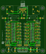
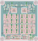
I have designed small stereo board based on Sapphire 4 including small pot.
Board size is 75mm * 80mm to fit to Hammond Case, It will be used with LT3081/ LT3091 PSU that I built with previous diamond buffer project.
I would like to share gerber after building it if you don't mind.
@RJM,
I have designed small stereo board based on Sapphire 4 including small pot.
Board size is 75mm * 80mm to fit to Hammond Case, It will be used with LT3081/ LT3091 PSU that I built with previous diamond buffer project.
I would like to share gerber after building it if you don't mind.
Attachments
@withmatt
Sure, go ahead. That layout looks like a pretty interesting take on the circuit.
My only request is that you post the gerbers to this thread, in addition to whatever else you have planned. Ideally the .brd files too.
One comment: Both our layouts relay on a wide area, shared ground plane for all the current returns. I never had any problem with ground loops or instability, but maybe I just got lucky. I would definitely recommend building and measuring a prototype first before finalizing the production layout.
@withmatt
Sure, go ahead. That layout looks like a pretty interesting take on the circuit.
My only request is that you post the gerbers to this thread, in addition to whatever else you have planned. Ideally the .brd files too.
One comment: Both our layouts relay on a wide area, shared ground plane for all the current returns. I never had any problem with ground loops or instability, but maybe I just got lucky. I would definitely recommend building and measuring a prototype first before finalizing the production layout.
Yes, I will share it to here also.
The power board has one wide ground plane, but amplifier board does not have big ground plane. I built two different ground plane for same circuit for previous project, star ground was better than one big ground plane.
Thanks. In principle a continuous ground plane is best, but in practice I have found that connecting the signal returns first before a shared connection to a power ground plane works better. This was based on tests with the Phonoclone, which is much more sensitive than the Sapphire due to the higher gain and smaller signal voltages however.
")
@ustas
I make it a point of always designing for 5% resistor values whenever possible. The BOM parts are 1% since metal film resistors are commonly available in that tolerance, but with the exception of the phono stage RIAA values you can always use the 5% values instead.
So 332 is 330 ohms, 221 is 220 ohms, 4750 is 4700 etc.
@ustas
I make it a point of always designing for 5% resistor values whenever possible. The BOM parts are 1% since metal film resistors are commonly available in that tolerance, but with the exception of the phono stage RIAA values you can always use the 5% values instead.
Thank you. You need add this info to the BOM.
What about custom BIOS calculator?
Hi
Maybe a silly question but i want to build ver.4,
i check schema and board in eagle. On schema tehere is nice ground path conencting gnd, zeneres, caps and etc.
But on board there is no connection. Is it right or something wrong is with my eagle ??
On print screens i shows what i worry about.
Maybe a silly question but i want to build ver.4,
i check schema and board in eagle. On schema tehere is nice ground path conencting gnd, zeneres, caps and etc.
But on board there is no connection. Is it right or something wrong is with my eagle ??
On print screens i shows what i worry about.
Attachments
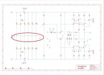
When you load the .brd file into Eagle the polygon fills are only indicated by a dotted outline. Click the "ratsnest" button to fill the polygons and properly display the Sapphire's ground plane.
Ok i do it, now it seems ok. But i just already ordered pcb from jlc, hope that gerbers will be fine ( i genereated these file wihtout cliking rastnest button).
Will see when pcb will come next week.
Also i have next question. How crucial are parameters of c10,11 bypass capacitors?? Then can vary slight?? And is it must be x7r capacitors ?
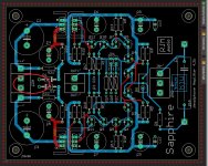
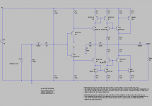
One of my recent emails was from someone asking about running the Sapphire from a single 12 V supply.
It's doable, with some performance hits due to the reduced voltage and asymmetrical design. The simplifications might be worth it for some however, so I'm thinking about at least making a board layout for it. It can be a headphone amp or a preamp/line driver.
Anyone else interested?
It's doable, with some performance hits due to the reduced voltage and asymmetrical design. The simplifications might be worth it for some however, so I'm thinking about at least making a board layout for it. It can be a headphone amp or a preamp/line driver.
Anyone else interested?
Attachments
You can just add a Jan Didden Silent Switcher, with which you can generate low noise +/-15V from a single supply as low as 5V (USB).
No need to compromise.
The SilentSwitcher | Linear Audio NL
SilentSwitcher - mains-free +/-15V and 6/5/3.3V power
Cheers,
Patrick
No need to compromise.
The SilentSwitcher | Linear Audio NL
SilentSwitcher - mains-free +/-15V and 6/5/3.3V power
Cheers,
Patrick
For portable applications, I have also used LTC3265, which is all in one.
https://www.diyaudio.com/forums/vendor-s-bazaar/283672-audio-op-amp-opa1622-6.html#post4953256
(Post #297)
Patrick
https://www.diyaudio.com/forums/vendor-s-bazaar/283672-audio-op-amp-opa1622-6.html#post4953256
(Post #297)
Patrick
some questions about
hello there
i want to build the sapphire v4 amp and i have couple of questions
1. the schematic looks symmetric. can i bypass input capacitor - if there about 0 dc in this point?
2. can it be scaled to drive small speakers? what changes will be needed for this (power source, parallel output stage transistor, etc)
3. where to buy pcbs or kits? maybe i can find all components to build the amp but i have no experience with making pcb.
thanks
- Home
- Amplifiers
- Headphone Systems
- RJM Audio Sapphire Desktop Headphone Amplifier