Some missing pictures
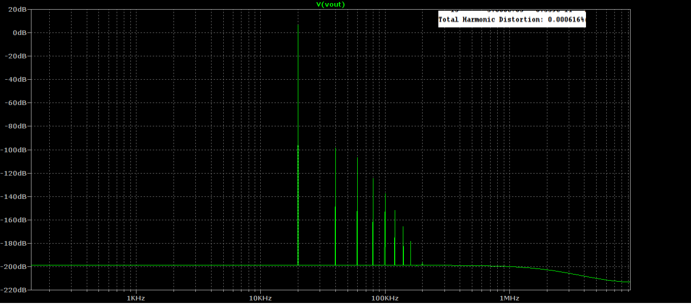
IMD 19=20kHz

I found it at the russian forum
Use google translate to understand text
???????? Hi-End - ???????? 4
IMD 19=20kHz
I found it at the russian forum
Use google translate to understand text
???????? Hi-End - ???????? 4
Last edited:

I've had the Sapphire 4.1 for quite a while now and while I like it alot, when listenting through my HD650 the sound feels much flatter and less dynamic than compared to my AMB CK2III.
Both amps have TKD 2CP2500 pots.
I have Mundorf supremes in the Sapphire, could that be the cause, or maybe its the gain?
It is currently set to 12dB, but based on the Gain calculator, the HD650 at 300ohms and 97db/mW (or 103db/1V) the gain should be 22-23. Does that make sense?
I found some 499R resistors and swapped those in (config is single gain, open loop), which brings gain to 21db.
Initial impressions are that things are much more "lively"
Richard, would like to get some insight into whether this makes actual sense or is it just in my head?
Based on what I read, Gain should only be increased if adequate volume cannot be reached, and doesnt affect anything else.
Previously, with 12dB gain, I could reach adequate volume slightly after the half way point of the pot, but things sounded flat.
Could gain also affect Voltage swing?
@itsikhefez
Running at low gain has a couple of consequences. First, you have to correspondingly have the volume control turned up more, which puts more impedance at the input of the Sapphire. It's a balance though as high gain has it's own set of negatives. Low gain also increases the amount of applied feedback. Within stability that actually lowers the distortion, but could in principle make it sound damped.
Short answer is I don't really know but most circuits I've tinkered with sound better with the gain adjusted to a sweet spot where the volume control around 9-10 o'clock gives the typical listening level.
@GRAALH:
Closer to Sapphire 2.5. I confess I'm not totally sure where you are aiming with it, but I'm interested enough to want to hear you introduce your output stage design.
Ready to try my Sapphire. Thanks Richard!!!
I want to do a selector like gain control as I saw in the thread. Any recommendation? I have seen that the values here differ from those in the Excel sheet. I'm going to use a "closed loop buffer" configuration.
On board R2210 (R3X) R100 (R2B) and selector with R332 and R1000 (R2Bx and R2By)


I want to do a selector like gain control as I saw in the thread. Any recommendation? I have seen that the values here differ from those in the Excel sheet. I'm going to use a "closed loop buffer" configuration.
On board R2210 (R3X) R100 (R2B) and selector with R332 and R1000 (R2Bx and R2By)
How to use connect a rotary switch to the Sapphire 41m boards to enable front panel gain selection.

Experimental. The inductance of long lead wires may cause stability problems, especially with the closed loop configuration.
I want to do a selector like gain control as I saw in the thread. Any recommendation? I have seen that the values here differ from those in the Excel sheet. I'm going to use a "closed loop buffer" configuration.
On board R2210 (R3X) R100 (R2B) and selector with R332 and R1000 (R2Bx and R2By)
The values are different because the rotary switch is configured to add resistances in series, while the on-board jumper adds resistances in parallel.
R3X is going to be on the board.
For the diagram pictured, R2A and R2C are omitted from the board, and the switch is inserted in series with R2B to optionally add resistance.
the gain settings are calculated using R3X and
R2B (high gain)
R2B+R2Bx (mid gain)
R2B+R2Bx+R2By (low gain)
Thanks!!
BOM for Sapphire 4.2b.
I've settled on 3300 uF and 330 uF, Nichicon FW or KW as the default filter caps for the new board. These scale to 4700/470 and 6800/1000 for the 75 mA and 150 mA version, also available from the FW/KW series.
There are no other changes.
I've settled on 3300 uF and 330 uF, Nichicon FW or KW as the default filter caps for the new board. These scale to 4700/470 and 6800/1000 for the 75 mA and 150 mA version, also available from the FW/KW series.
There are no other changes.
Attachments
BOM for Sapphire 4.2b.
I've settled on 3300 uF and 330 uF, Nichicon FW or KW as the default filter caps for the new board. These scale to 4700/470 and 6800/1000 for the 75 mA and 150 mA version, also available from the FW/KW series.
There are no other changes.
Richard,
I have been following these changes and I was wondering why you preferred the Z-Reg based power supply, not the X-Reg?
Would not the X-Reg concept have any improvement in your opinion?
Best Regards
I haven't experimented, but the Z-Reg is my go-to choice for anything but very low noise circuits. The X-Reg overcranks things (too much feedback) .. it's been superseded with the shunt-source S-Reg in my new phono stage designs.
I have finished my amplifier.
It seems that everything is correct but one of the channels I have only been able to reach -400mV offset. The other channel is perfect (0 ~ 5mVolt).
I have noticed that when I change the gain selector, the offset increases considerably only on the channel with problems.
I am started to check voltages. The components seem to be in order.
Richard please, Do you recommend checking something in particular? Q1 and Q2 maybe?
If -400 mV is the offset with the trim pot at one extreme, what is the offset with the trim adjusted to the other extreme?
Did you build from my kit or with your own parts? The kit has graded transistors but if are using your own it's possible that a really oddball transistor can throw off the Vbe balance. That said the more likely probability is one of the transistors is connected to the board incorrectly, or perhaps got overheated during soldering.
The other problem that sometimes occurs is the Zener diode values are radically different. Please check V+ and V- to make sure they are close to each other in absolute value.
R
Yes I used my own parts.Ready to try my Sapphire. Thanks Richard!!!
I want to do a selector like gain control as I saw in the thread. Any recommendation? I have seen that the values here differ from those in the Excel sheet. I'm going to use a "closed loop buffer" configuration.
On board R2210 (R3X) R100 (R2B) and selector with R332 and R1000 (R2Bx and R2By)
With trimpot R6 in the middle I had -1volt.
+V and -V are 10,77v and -10,82v... other channel has a value little lower, arround 10,67v and -10,52v but it work fine.
Last edited:
I have retouched some solders with the help of my microscope and the channel works perfectly. It sounds very good Richard!!
When I change the gain (via selector) the offset varies a little from 0 ~ 5mVolt after 5 ~ 10mV and finally reaches 20mVolt. At first I do not think it's anything to worry about.
When I change the gain (via selector) the offset varies a little from 0 ~ 5mVolt after 5 ~ 10mV and finally reaches 20mVolt. At first I do not think it's anything to worry about.


- Home
- Amplifiers
- Headphone Systems
- RJM Audio Sapphire Desktop Headphone Amplifier