It probably bears some experimentation, but by default I would leave them in.
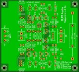
I went ahead and retained C10-C17 on my PCB layout using a separate regulated PS like the Jung Super Regulator.
I don't own a scope to do any measurements or comparisons with, so experimentation is limited on my end.
Do you think keeping C10-C17 on the board is sufficient and/or okay?
Attachments
It comes down to the interplay of the capacitance and trace inductance at high frequencies. The idea is to keep capacitance close to the amplifier circuit to provide low impedance bypass connection from the output ground to the power supply rails.
Yes, the superreg output is itself low impedance - due to the high feedback of its design - but there is separation between it and the amplifier which adds impedance and can cause other problems besides. Although the Sapphire has so far proven to be remarkably stable, I can't guarantee it will work without sufficient bypass capacitance and I have no data to guide you on how much or how little you will need with your build. The Superreg itself may or may not like to have capacitance on its outputs, so that's another consideration.
I'd suggest a few hundred uF and some ceramic 0.1 uF bypass caps as they are positioned on the existing board should keep everything copacetic. They might be unnecessary, but on the other hand I don't think you'll need more than that.
Last edited:
I'd suggest a few hundred uF and some ceramic 0.1 uF bypass caps as they are positioned on the existing board should keep everything copacetic. They might be unnecessary, but on the other hand I don't think you'll need more than that.
I kept three 100uF caps and one .1uF cap per rail as shown on my board above.
That's why I posted an image showing I left them in the same location as your boards.
Would that not be considered a few hundred uF?
I have other regulated supplies that I can try. The Jung is my favorite with op-amp circuits. I haven't tried it with any discrete circuits.
Most of my regulated supplies are set for around +/-12VDC.
I measure +/-11.5VDC on the boards with matched Zeners that I got from you?
So, is there a voltage range that you recommend?
Without changing any resistances, 9-15 V is probably a reasonable range for the power supply rails.
And yes, as you have the board configured above would meet what I'm arbitrarily saying is sufficient. But since you have space, you might add optional some 1000 uF just in case.
And yes, as you have the board configured above would meet what I'm arbitrarily saying is sufficient. But since you have space, you might add optional some 1000 uF just in case.
Richard, if using a separate PS like the Jung Super Regulator, can I eliminate all of the 100uF and .1uF caps or is better to leave them on the board?
Thanks.
I'm using an external power supply, and a general rule for most regulators is that large capacitance after the regulator should be avoided.
However, instead of removing the capacitors from the board I would advise to use the existing places and install lover capacitors, and mix electrolytic with some film one (which are large by design)
So instead of 2x1000uF on the input install electrolytic 47uF 50V + 4,7uF to 10uF MKP.
That is what I did and works like a charm.
Removing all capacitors from board would be very bad idea - proved in some previous projects - lesson learnt the hard way !
I'm using an external power supply, and a general rule for most regulators is that large capacitance after the regulator should be avoided.
Can you explain the reason better? And also if you can, explain how to calculate the proportion of capacitance from before regulation to after?
Can you explain the reason better? And also if you can, explain how to calculate the proportion of capacitance from before regulation to after?
There is no such thing as the right proportion. To simplify - before is good, after is bad. It just the way it is. Much depends on the regulator design, but most regulators works this way.
There is of course a point were increasing filtering capacitance make no sens, and too much could be bad as well ... but you are not likely to reach this point, unless you build a batery of caps that goes in really high number. An a few 100uF capacitors spread over the board is not a large value. Just the two 1000uF capacitors on the board input should not be mounted - these are smoothing capacitors required to 'smooth' DC pulses from the rectified AC voltage coming from the bridge.
There is much to read on the Internet, you can examine datasheet of the regulator in question, no need to break the doors that are already open, here is a good and simple explanation:
power supply - Why is a capacitor before a voltage regulator more effective than after? - Electrical Engineering Stack Exchange
And for sure uncle google can provide more.
To quote from the above source:
"The output capacitor should be as small as possible, just enough to bridge the time when the regulator responds and compensates for the increased load. Roughly speaking, if you increase the output cap you just hardening the work of the regulator."
However, you need to add (possibly low-ESR) capacitors to every utilization point to mediate the high impedance of the wire/PCB track after the regulator. For this reason you should keep small capacitors on board close to the power utilization take place.
So, don't remove the caps from the board, just make their capacitance smaller , and try lowering ESR (use right type) and use decoupling film capacitors with low dissipation factor tan δ.
I used small capacitance Rubycon ZL series caps rated for 50V.
I personally see no benefit in modifying the PCB just because you want to use a regulated power supply. If you want to make it smaller, than OK, otherwise - no.
Last edited:
just enough to bridge the time when the regulator responds and compensates for the increased load.
Yes, that would be an ideal situation, but no, there is no value of capacitance, large or small, that would provide this compensation exactly. The larger the capacitance and the lower the related inductance, the less droop you will observe on the regulator output in response to a step-change in the current load.
Large capacitors on the regulator output do not make the regulator work harder - they do exactly the job you expect, make the output voltage fluctuations less for the same "work" done by the regulator.
However, there is a long list of reasons why a large capacitor on the output of a regulator is bad idea. The higher the performance of the regulator (the more feedback used to reduce output impedance) the worse of an idea it becomes.
All this talk of regulators got me thinking though: power amplifiers do not normally use regulated supplies and no one gets especially upset, there is an argument to be made that headphone amplifiers don't need heavily regulated power supplies either. Some people even suggest unregulated supplies, but I'm not convinced that's the way to go. I do wonder, though, if a relatively light touch here might be preferred.
Last edited:
I personally see no benefit in modifying the PCB just because you want to use a regulated power supply. If you want to make it smaller, than OK, otherwise - no.
I didn't modify the board for any "benefits" per se. If the other components of the original regulator aren't going to be used, then I'm going to eliminate them.
A few clicks of the mouse and they're gone and the board's size is also reduced as you noted.
After thinking about it, I don't think the 1kuF caps are needed if using a separate supply with its own output caps.
The Jung regulator uses 120uF output caps. Connecting the Jung's outputs directly to 1kuF caps makes no sense to me.
I agree that they're more for smoothing the DC from a rectifier.
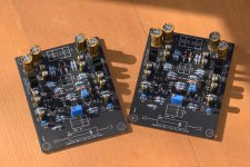
I've changed out the Sapphire 3 boards in my line preamplifier for this Sapphire 4 build.
For your reference, it is the standard "preamp" mod as described in the BOM, R15,16 1k, R17-20 47R. The gain configuration is open loop, R3 10k, R2A 10k, R2B 10k and R2C 3.32k for switchable 3-6-9 dB gain.
I chose these low gains as my amplifier was basically designed to use with a passive pre, and I listen at low volume anyway, so 3 or 6 dB gain is sufficient.
I chose the open loop option since at these low gains there is already plenty of feedback to lower the distortion of the voltage amplifier, there is arguably no particular need to temp fate and crank up the feedback by moving to the R3X option.
The BC327 and 337 were binned but I did not try to match Q1,2. Offset of one channel trimmed easily, the other was outside of the trim range of R6. The input offset is about 0.6 V ... almost a full diode drop, so something doesn't seem right. Investigating...
Attachments
Last edited:
The problem was traced to Q4 on the right channel, which I'd soldered in reversed 180 degrees, opposite to the silk screen - because. Because, already! 
(I am still wrapping my head around the fact that reversing this transistor actually changed very little of the dynamic circuit performance, merely unbalancing the DC offset a little. It's like a 7 legged spider, still 90% combat effective.)
One of the nice things about working with the Sapphire at very low gain is the offsets are so much less, and super easy to trim. With 5k trimmer, there is no need to worry about measuring the transistors. Just stick 'em in and trim 'em out.
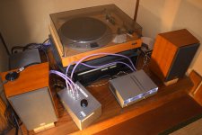
Just checked it all worked, with the Chromecast Audio as a source. That's the little puck on the left speaker. Amazing really...
Having a preamp with the correct gain is so nice. No extra noise, and fine adjustment with the volume in the sweet spot.
(I am still wrapping my head around the fact that reversing this transistor actually changed very little of the dynamic circuit performance, merely unbalancing the DC offset a little. It's like a 7 legged spider, still 90% combat effective.)
One of the nice things about working with the Sapphire at very low gain is the offsets are so much less, and super easy to trim. With 5k trimmer, there is no need to worry about measuring the transistors. Just stick 'em in and trim 'em out.
Just checked it all worked, with the Chromecast Audio as a source. That's the little puck on the left speaker. Amazing really...
Having a preamp with the correct gain is so nice. No extra noise, and fine adjustment with the volume in the sweet spot.
Attachments
Last edited:
Thoughts on using the Sapphire 4 as a preamp.
As my first major stab at a discrete transistor gain stage, I'm still surprised Sapphire 4 works. No hum, no heat, no noise, no distortion, no instability. Open loop or closed loop, high bias current or low, gain from 3 dB to 27 dB, the circuit is build-and-go, needing nothing more than a set-once-and-forget offset trim.
It's not too surprising that what works as a low noise headphone also works are a preamp though. The preamp mod bias current of 5 mA is ideal for loads 10k or above. For 600-10k range, the regular headphone amp configuration at 40 mA is preferred. That's the only difference between the two variants.
It might seem an awful lot of trouble to go through just for 3 dB voltage gain, but that gain also comes with an output impedance of 25 ohms to drive the amplifier and interconnects, as well as excellent PSRR and distortion characteristics. I've tried passive preamps and they just sound weak sauce. My power amplifier likes a low impedance drive, and the extra little bit of voltage gain does make a difference in how powerful the whole rig feels.
I won't make any substantial comment on the sound quality. A preamp is hard to evaluate at the best of times and I have no reference to A/B against. It sounds clean, and very very quiet. Upstream components are more clearly distinguished, and there is no tangible feel to the volume adjustment: loudness changes, but with no loss of resolution or clarity at low volume, and no sense of fade out or strain at higher volume. Definitely recommended, even if I can't say it sounds one way or another. I'm not convinced I can hear it but for it's absence.
P.S.
The Sapphire 3.1 I was originally considering to use as my next preamp is for sale. It's still set up as a headphone amp, 15/25 dB gain, with the 995 FET modules.
Last edited:
I haven't tried the open loop preamp configuration, only the closed loop with 6dB of gain.
So this circuit is stable with only 3dB of gain?
Reason I'm asking is because the BOM gain calculators(open and closed loop) only go down to 6dB. I was skeptical about going down to 3dB because some amplifiers oscillate if the gain is too low.
So for 3dB gain open loop, all I need to do is make R3 and R2A both 10k?
Thanks.
Hi ammel,
I left out that setting to keep the open and close gains consistent. I didn't think of anyone needing it, until I needed it myself! But, yes, it seems to work just fine at R3 10k and R2A 10k. The open loop config has excellent phase margin even at 3 dB, so stability is not a concern.
I left out that setting to keep the open and close gains consistent. I didn't think of anyone needing it, until I needed it myself!
But, yes, it seems to work just fine at R3 10k and R2A 10k. The open loop config has excellent phase margin even at 3 dB, so stability is not a concern.Hi Richard,
Having tried your Sapphire 4 as a 6dB gain preamp in both the open and closed loop configurations, I have to say I prefer the sound of the open loop configuration.
IMO the mids and highs seem to be a little more "present" than with the closed loop configuration, which sounded a little more "dark" and "closed in" for my taste.
Also, the bass response of the Sapphire 4 is excellent and notably better than any of the op-amp preamps(VGS + CFA) I've been using.
For the PS, I didn't even use separate transformers and rectifiers for each board. Just a simple and reliable Rat Shack 12V-0V-12V 3A transformer and a single bridge rectifier for both boards.
Input caps were inexpensive Dayton Audio 1uF 250V 1% tolerance caps:
Dayton Audio PMPC-1.0 1.0uF 250V Precision Audio Capacitor
Using better input caps may improve the sound even more...I don't know.
Perhaps more people on this site will build the Sapphire 4 and try it as a line stage if they're looking for a great sounding line stage that's easy to build AND still uses good old through-hole components instead of SMDs.
Last edited:
Thanks for the report, both for the open/closed loop comparison and confirmation that it all works cleanly with a shared power supply.
The Sapphire 4 is a great diy preamp, but I sense that discrete solid-state line preamplifiers are one of the least popular things to build around here. It's just not something people tend to bother with. Let's just say I'm not anticipating a stampede of activity, even after your positive evaluation ...
The Sapphire 4 is a great diy preamp, but I sense that discrete solid-state line preamplifiers are one of the least popular things to build around here. It's just not something people tend to bother with. Let's just say I'm not anticipating a stampede of activity, even after your positive evaluation ...
Thanks for the report, both for the open/closed loop comparison and confirmation that it all works cleanly with a shared power supply.
The Sapphire 4 is a great diy preamp, but I sense that discrete solid-state line preamplifiers are one of the least popular things to build around here. It's just not something people tend to bother with. Let's just say I'm not anticipating a stampede of activity, even after your positive evaluation ...
You're welcome. I hope to get more matched transistors and Zeners from you for future builds. I'll be sending my own Gerbers off in a few days to get some boards made.
If other people don't bother with it, then I feel that's their loss. Most passive preamps sound "sterile" and just don't do it for me.
Call me old school or whatever, but I like a low gain active line stage between my source and power amplifier to "flavor" the sound.
Sapphire beyond the headphone amp?
In my experience, the preamplifier in a system is the toughest component to get right and, for me, it's most often the limiting factor in achieving satisfaction in overall sound - room effects notwithstanding.
Even though I've accumulated more caps, transistors, resistors, diodes, etc to build a second set of Sapphire boards to try the closed loop configuration, I'm mired in inertia because I am so pleased with my open loop boards. I really enjoy my Sapphire, but I have ample space for speakers and separate components and I do listen to them as much - even more - as I do my HA. So a Sapphire-based preamp is actually pretty appealing. It's the secondary aspects of a pre-amp that might hold me back - connectivity for other components - tuner, CD, turntable inputs, etc. Or dual subwoofers. Some will tell me to connect them via high-level speaker connections, but I'm not so sure.
It's the secondary aspects of a pre-amp that might hold me back
Exactly. You, me, and everyone. The gain stage is the easy part. It's deciding what you want your preamplifier to do, and implementing that, which is hard. As well as input switching, there are mute, mono, and R/L invert switches, recording buffer, headphone output, phono preamp, as well as remote control functions to consider. It is quite dizzying.
Here's the blog entry for my preamplifier build, written back before I subbed in the Sapphire 4 boards. It just has a mute switch and two line inputs as "features". Working out the physical layout (which connectors and switches would be placed where, and how I would wire it all up) took far more time than putting together the boards.
Last edited:
- Home
- Amplifiers
- Headphone Systems
- RJM Audio Sapphire Desktop Headphone Amplifier