Sounding great
I'm still wondering why one channel worked while the other didn't after I made the boards as identical as I could.
I had only a few minutes before other obligations took over the day, but my first impressions are of a lush and enveloping soundstage, with perhaps some warmth as in the sense you've suggested, yet no less precision than my 3. My 3 was running AD8610 op-amps. It doesn't help that I have been listening in the last couple of days to an old Sony Discman whose lith-ion batteries I'm trying to resuscitate so I can give the thing to a non-technophile neighbour. Compared to the discman, Sapphire 4 sounds astoundingly good, so good that I won't feel any desire to put the 3 boards back in, even though I probably ought to for a better comparison. More listening to both is needed. My C1 caps are, of course, already well broken in.
I took advantage of this reconstruction to fit mu-metal shielding around the torroidals, and a laminated mu-metal and brass barrier wall between the bridges and the pcbs. I daresay this has cleaned things up a bit no matter which boards I'm listening to.
I wonder if your trim pot R6 was busted? Did you verify you could adjust the bad board output offset between say -6 V and -1.7 V over the full range of the pot?
I ask because having run through the numbers and double checking with LTSpice, I can't find any mistake. LTSpice calculates the untrimmed DC offset to be -1.7 V, exactly what you measured. (the sim data hfe values appear to be 385 for BC327 and 292 for BC337) LTSpice also reports that to trim that requires +80 mV to be added at the input, requiring 1.5k of resistance imbalance.
To trim this with the 2k pot would require it to be turned about 85-90% up. In line with what you reported for your good channel.
Adding 1.5k to R5 does exactly the same thing.
The numbers at any rate are all consistent with everything normal except for R6 nonfunctional (1,2 shorted or the screw mechanism broken). The only other explanation would be for the hfe of Q1,2 to differ by 200, or a 100 mV or greater difference in V+ V-, both of which your own measurements eliminate as possibilities.
However, I have learnt my lesson: R6 will be changed to 5k in the next BOM revision to avoid any possibility of anyone straying out of the trim range.
Last edited:
As installed, R6 started off giving a value of about -4.something volts and turned down to -1.7 v, then -1.3 v, then -.28 v, so I think it is working properly. I didn't try changing trimmers after the resistor trick worked.
I seem to recall that Bourns offers trimmers with a small number of turns or a large number of turns, in the same values. You'll want lots of turns for fine resolution, right?
I seem to recall that Bourns offers trimmers with a small number of turns or a large number of turns, in the same values. You'll want lots of turns for fine resolution, right?
Yeah. The Vishay T93YA in the BOM is a 10 turn trim.
Anyway, I give up: There is for some reason unknown to me slightly more variation in DC offset values than I can predict based on how the circuit and the transistors operate in simulation, calculations, or even my own practical experience. It's not a huge discrepancy... an unluckly combination of additive factors might conspire to throw the offset out of the trim range. The main thing is to allow sufficient adjustment to compensate for it.
BOM 4.0b8 attached. R6 changed to 5k. (this is a record for highest revision number on any of my projects.)
Attachments
Last edited:
Wait did you say -4 V to -1.7 V? That's exactly half the range expected for the 2k trimmer.
I wonder if my earlier suggestion stands? That pin 1 and 2 of the trimmer are shorted together. That would mean you could add 2 k to R4, but would be unable to adjust R5. You would get a trim range of -2.5 to 0, but not the 0 to +2.5 you would have needed to compensate for -1.7.
Easy to check: measure the resistance between pin 1,2 and pin 2,3 with the trimmer adjusted about half way, should get 1k between each. If 1k and 0 we know the cause of your pain.
I'll check the trimmer tomorrow. Tonight I've been listening. I'm thinking the soundstage seems more cohesive and I am surprised at the fullness of bass notes in some tracks, as if I were listening to "Bass boost 'phones" (I'm not). Very, very impressed with this, I could just leave these boards in my little Sapphire box from now on.
Further and hopefully final comment on R6.
I checked one of my boards for the untrimmed output offset and measured -0.7 V. This is in line with what I'd have expected based on the hfe values I used for Q1 and Q2, which differed by about 40, and factoring in some influence from the 50 mV mismatch in the power supply voltages. It can be easily trimmed with R6=1k.
However not everyone building this is going to be matching Zeners or even transitors, and the worst case variation can get quite staggeringly high.
Making R6 large to cover all possibilities however makes the trim adjustment more difficult, since the same movement of the trim control moves the output more and more quickly.
I think 5k is a reasonable compromise, but I still think that 2k should be fine if you have closely matched the relevant components. I consider what happened to Stan's second board to be an anomaly - even if it should prove that R6 was functioning properly. 3 of the four channels built (one of his, two of mine) fully behaved as expected, only one did not.
I've attached the trim worksheet again that I uploaded earlier. Slightly revised to be easier to understand. It might be helpful as a guide if you know already what range of hfe values you will be working with and want to know if you can use a smaller value for R6 or not.
Attachments
I'm back, I suspect a critical drive is suffering from old age.
One side of R6 appears to be duff. "OL", says Fluke; the other side measures 271mv, which sounds like what it took to zero the channel. I didn't bother turning the screw to mid-point.
So I think I'll see if I can get another 2K trimmer and try that.
I will say again that Sapphire 4 sounds awesome, duff trimmers or no.
We could go with that, I don't have a preference. The Type 3296W I think it is, the Mouser p/n in 5k is 652-3296W-1-502LF.
There's also a 3299W which apart from being 1 mm wider body appears identical.
****
Measurements:
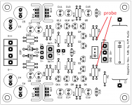
Either measure resistance between pin 1,2 and pin 2,3 with the power off or voltage across the same pins with the power on. A quick-and-easy test with the boards powered up and without having to dive to the underneath of the boards to find the pins of the trimmer is to check the voltage between the exposed leads of R4 and R5 located closest to the trimmer.
For R6 = 2k it should measure about 220 mV (22 V * 2k/202k) and will not change with the trim position. Constant 220 mV means "probably good", variable 0 - 220 mV condition is "definite short".
There's also a 3299W which apart from being 1 mm wider body appears identical.
****
Measurements:
Either measure resistance between pin 1,2 and pin 2,3 with the power off or voltage across the same pins with the power on. A quick-and-easy test with the boards powered up and without having to dive to the underneath of the boards to find the pins of the trimmer is to check the voltage between the exposed leads of R4 and R5 located closest to the trimmer.
For R6 = 2k it should measure about 220 mV (22 V * 2k/202k) and will not change with the trim position. Constant 220 mV means "probably good", variable 0 - 220 mV condition is "definite short".
Attachments
Last edited:
I picked up a pair of Bourns 25-turn 2K trimmers today, 3296W-1-202.
I thought the suggested value was 5k ohm now for more adjustment range?
I would be surprised if a trimmer was bad unless it was overloaded in some way.
I buy the 3296 Bourns copies from China and have never had one of them fail...knock on wood.
I give up, too.
I took the board right out and could get a better purchase on the trimmer to measure it. It seems to be fine, resistivity both sides. So it's all back together with kludges intact and unseeable in the case anyway. Back to listening, and forget about why one board worked and one didn't.
I took the board right out and could get a better purchase on the trimmer to measure it. It seems to be fine, resistivity both sides. So it's all back together with kludges intact and unseeable in the case anyway. Back to listening, and forget about why one board worked and one didn't.
I think OL means no continuity. Somebody will correct me if I'm wrong.
Not if you are measuring volts it doesn't! It stands of "overload". For resistance, it means the test current returns a voltage that is out of range, aka open circuit, for millivolts, it means the measured voltage is above the maximum range, ditto volts also.
- Home
- Amplifiers
- Headphone Systems
- RJM Audio Sapphire Desktop Headphone Amplifier