Well, it was common in Japan until quite recently. Certainly anything built before ~1975 are just simple 2-wire. In older houses you'll most often see runs of zip cord just stapled to the wall.
For your amusement I'm attaching a photo of the main circuit break out box in my house. I'm in there fairly often, as using the toaster at the same time as the electric kettle trips the kitchen circuit. Dispite being built in the 1970's, the kitchen has no provision for a fridge. You are expected to use the pantry, under a trapdoor in the floor, or the insulated cupboard which I think was used as a small icebox.
It could be worse. I remember refusing hot showers in South America as it was often an electric element with exposed wires on the shower head. Not for me, nothing like starting the day with a brief and cold refreshing shower
ESP's tutorial on earthing came up in a recent blog post.
It may be, as they say, relevant to our interests. I haven't tried it, though I might give it a shot. I would have though that simply lifting the safety earth would amount to the same thing in terms of noise pickup. So if doing so makes a big improvement then you can achieve the same result and still maintain the safety connection by using the bridge rectifier arrangement illustrated.
It may be, as they say, relevant to our interests. I haven't tried it, though I might give it a shot. I would have though that simply lifting the safety earth would amount to the same thing in terms of noise pickup. So if doing so makes a big improvement then you can achieve the same result and still maintain the safety connection by using the bridge rectifier arrangement illustrated.
Attachments
That's how I have my Sapphire wired up. I used Boskie's House Ground Kit.
Does it make any difference?
Unfortunately for me, it doesn't. In fact my (slight) buzzing in the left channel doesn't depend on even having a source component plugged in, nor does it depend on whether the chassis is earthed or not.
I've narrowed it down to the asymmetry of the case layout - the left channel is sitting next to the front panel power switch - or a fault in the left channel board/wiring somewhere.
Next thing to try is cutting out the switch and AC wiring to the front panel. If that doesn't make any difference I'm left combing the board for a cold solder joint or hair fracture.
I see. Actually I've just done the same thing with mine, cutting the front panel AC switch out of the circuit and hardwiring the Sapphire3 as "on" so long as the power cord is plugged in.
This has leveled the noise balance L-R. The residual noise, I now realise, is just pickup from the power supply which I naively assumed would be okay to install next to the Sapphire boards with no particular concerns for shielding. The issue is not the transformers or diodes per se, at least not to a significant degree, but the general noise which is present on the AC line.
This is only becomes a concern when the Sapphire3 is used in conjunction with a computer/monitor/router etc. and at the same time a high-end, low noise source. So the input signal is low noise but the power supply is unusually noisy.
My next trick will be to replace all the chassis wiring with shielded twisted pair. That should probably kill the problem dead. The real solution though is to rebuild it either as a two box unit or as a single chassis with metal dividers and a decent amount of distance between power supply and amplifier.
As it is now even it is not noisy by any reasonable definition. You can turn the volume to max with the inputs left open circuit and hear only the faintest rush or hum, unless there is switching power supplies on the same circuit, in which case there is a distinct crackle.
FWIW - if you take a closer look at the picture in post 573, you'll note the primary side caps are 1500 uF each, Panasonic FR low ESR, high ripple - so 1,000 uF more on each primary rail than the standard kit.
On the secondary side are a pair of 330 uF (Panasonic FR's I think) and a pair of 220 uF (Rubycons?), and where C15 and C16 go is a pair of WIMA PP MKPs 0.1uF on the bottom side. The WIMAs are probably a waste of parts.
I'm also lucky to have a fairly modern 3-wire AC system. But, all the power is coming from the same socket for the headphone amp, computers, modem, wireless router, laptops, etc. For audio, it's coming from a USB connection through a Schitt Wyrd - pretty much a fancy powered and filtered hub with re-clocking - it got rid of some of the high frequency hash.
And in picture in post 580, lower left there the house ground and the brass post is chassis, right next to the AC cord and fuse.
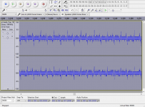
dont know if this is what your after Richard. i took the headphone line out and plugged it into the microphone input of the computer and recorded events. recording level was set at 90. the cable i have is a bit dodgy.
the first 10 or so seconds was nothing, i then turned on the Sapphire (single large spike) Sapphire is at full volume due to not having a conventional volume pot, i then turned on the Raspberry Pi (2 large spikes), i then played a blank flac file that i generated in Audacity (last spike) volume was at about 2 o'clock '70' in MoOde.
looks like its not that quiet after all and to me it looks like i have a channel imbalance.. hhmmm
the first 10 or so seconds was nothing, i then turned on the Sapphire (single large spike) Sapphire is at full volume due to not having a conventional volume pot, i then turned on the Raspberry Pi (2 large spikes), i then played a blank flac file that i generated in Audacity (last spike) volume was at about 2 o'clock '70' in MoOde.
An externally hosted image should be here but it was not working when we last tested it.
looks like its not that quiet after all and to me it looks like i have a channel imbalance.. hhmmm
In Audacity you can record the output with the volume turned down. Everything as quiet as possible. Then use the "effects|amplify" function to scale it all up so you can see it. Use the analyze|plot spectrum to see the FFT, and you can export the data to excel if you like.
Note that the FFT will shift up of down with the amplify setting so if you want the true y-scale you should plot and export before applying the amplify.
On Windows Audacity records 16 bit regardless of the computer setting.
See below for my most recent results. Finally, I can see my enemy.
recent changes:
- removed the AC wiring to the front panel switch, connected the transformer primaries directly to the rear IEC jack.
- added a 0.47 uF film cap across the AC line (if doing this, you should formally use an X or XY type supression capacitor)
- removed bypass cap C22,23 next to the op amp.
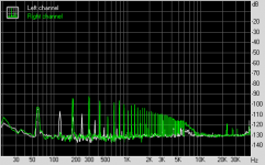
The audacity screenshot is after +70dB amplification.
We can see that the residual "frill" of harmonics in the audio spectrum is due to tiny spikes at 120 Hz due to diode conduction. That is the only residual signal above the software imposed 16 bit resolution floor. Rightmark (with the volume turned up and inputs connected) gives the same result, so its clear the interference is internal to the Sapphire circuit, un-associated with the input signal.
Note that the FFT will shift up of down with the amplify setting so if you want the true y-scale you should plot and export before applying the amplify.
On Windows Audacity records 16 bit regardless of the computer setting.
See below for my most recent results. Finally, I can see my enemy.
recent changes:
- removed the AC wiring to the front panel switch, connected the transformer primaries directly to the rear IEC jack.
- added a 0.47 uF film cap across the AC line (if doing this, you should formally use an X or XY type supression capacitor)
- removed bypass cap C22,23 next to the op amp.
The audacity screenshot is after +70dB amplification.
We can see that the residual "frill" of harmonics in the audio spectrum is due to tiny spikes at 120 Hz due to diode conduction. That is the only residual signal above the software imposed 16 bit resolution floor. Rightmark (with the volume turned up and inputs connected) gives the same result, so its clear the interference is internal to the Sapphire circuit, un-associated with the input signal.
Attachments
Last edited:
Leave it connected to the Pi. That's fine for the moment and anyway gives you a true picture of the system as a whole.
Yes, the data exports as a text file. To actually see it though, you can copy-paste to Excel or similar to plot a graph. Sometimes the native plot in Audacity is off scale and the peaks aren't visible.
Richard
Yes, the data exports as a text file. To actually see it though, you can copy-paste to Excel or similar to plot a graph. Sometimes the native plot in Audacity is off scale and the peaks aren't visible.
Richard
Your soundcard/mobo will need to have a reasonably decent input section A/D to discern the Sapphire output noise over its self-noise baseline. Most modern PCs should be okay though. I just checked and even the line in of my Dell speaker bar (AC511) is quiet enough - and that's hardly a high-value part.
It's worth making a measurement without anything plugged into the line in to see how it will shape up.
It's worth making a measurement without anything plugged into the line in to see how it will shape up.
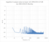
For those who might be interested here is the breakdown of the Sapphire3 power supply and ripple.
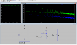
12 VAC per rail gets rectified and fed to the Sapphire3 circuit boards where the first thing they see are 2x1000 uF filter caps. The resulting voltage Vin is the V++, about 16 VDC with a 300 mV p-p sawtooth edge riding on top. This would be pretty nasty sounding, but fortunately it is smoothed out into a heavily distorted sinusoidal waveform about 100 microV p-p at the output of the Zener-based voltage regulator (Z-reg) Vout.
The noise on the DC voltage feeding the op amp and buffer circuit, V+, is simulated by the blue trace in the LTSpice screengrab below. The largest peak is less than -80 dB at 120 Hz. That would still be a problem, technically, except that it is mopped up by the PSRR of the op amp (above 60 dB below 10 kHz) and the buffer (also above 60 dB below 10 kHz).
So, typically, the ripple in the output can be expected to be -90 - 60 = <-150dB dB from the buffer, and -90 - 60 + gain 27 dB (in my case) = <-123 dB from the op amp). That's a conservative estimate, as at the lower frequencies where the Z reg noise is highest the circuit PSRR is also better.
It is doubtful any noise spikes would be seen in the output at all.
However, I do see a noise pattern in the output at -100 dB that looks very similar to the noise in the V++ rail. The most likely explanation, therefore, is that the output noise is produced by coupling to the V++ either through free space or through a shared ground trace. The latter is unlikely, as the layout does not make such an error. I'm left with pickup through free space, i.e. a shielding problem. Unfortunately it varies little with volume, meaning it is induced not in the input wires to the RCA but in the section after the volume control which is harder to deal with as it includes the circuit board itself and not just chassis wiring.
Attachments
Last edited:
best i can do. recorded with RPi off and recording level at 100. amplified at 50 as thats the max it would allow.
An externally hosted image should be here but it was not working when we last tested it.
That's progress! Actually you can call the amplifier function again and set the number to less than 50 dB to scale the view further, but what you have there is sufficient. You can try looking at the FFT, or zooming in the time scale to see if there is any 60 Hz hum or ripple noise in the recorded signal above. Interesting that your output signal seems to drift a little over the seconds time scale.
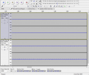
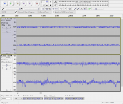
Here's my setup, after applying the same 50 dB amplify to the recorded data, and for 70dB (50+20). Top track is the line input with no connection, bottom track is with the Sapphire3 connected, powered, volume 0. The limited resolution is due to Audacity recording in 16 bit despite the 24 bit ADC in my soundcard due to licensing restrictions.
Here's my setup, after applying the same 50 dB amplify to the recorded data, and for 70dB (50+20). Top track is the line input with no connection, bottom track is with the Sapphire3 connected, powered, volume 0. The limited resolution is due to Audacity recording in 16 bit despite the 24 bit ADC in my soundcard due to licensing restrictions.
Attachments
Last edited:
soundcard plugged into the Sapphire without the Sapphire being on.
i cant take a reading with the cable on the soundcard unplugged, it wont let me.
Sapphire on and RPi on with a silent track playing at 1 on volume.
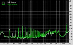
spectrum, yup a bad 50hz.
i cant take a reading with the cable on the soundcard unplugged, it wont let me.
An externally hosted image should be here but it was not working when we last tested it.
Sapphire on and RPi on with a silent track playing at 1 on volume.
An externally hosted image should be here but it was not working when we last tested it.
spectrum, yup a bad 50hz.
An externally hosted image should be here but it was not working when we last tested it.
- Home
- Amplifiers
- Headphone Systems
- RJM Audio Sapphire Desktop Headphone Amplifier