Those voltages are good. The regulators (the 7812 and 7912) need at least 15 volts to work, and less than 36 volts which is their maximum rating. So all good so far.
Next step is to check the regulator outputs which is easily done by measuring the voltage on D1 and D5.
D1 should have +12 volts on the non striped end and about +11.3 on the other end.
D5 should have -12 volts on the striped end and about -11.3 on the other end.
Those lower voltages (the - and + 11.3) should then be present on pin 8 of U2 (+11.3) and pin 4 of U2 (-11.3)
I've no idea what the upgraded parts list refers to but assuming U2 is the correct type then you should have -12v on pin 4 and + 12v on pin 8.
Are they present and is U2 the correct type ?
So the pins on U2 measure,
p1 -11.8
p2 -9.2
p3 -10
p4 - 11.82
p5 - 10
p6 - 11.8
p7 -8
p8 11.78
And the part I am using is 513-NJM2903d
The problem is around the second half of U2.
Pin 5 is more positive than pin 6 (which is correct) and that should flip the output to a positive voltage (which isn't happening).
Not many possibilities for this. Always possible the IC could be faulty but that would be last on the list.
I suspect your problem is either physical (a short or break in the print) or a problem around or with the FET Q2.
With the FET removed you should see pin 7 become a positive voltage. If it does then the FET is faulty or it is not what its supposed to be. Make sure there are no whiskers of solder (that could cause a short circuit) on the FET connections on the board.
Also make sure you have continuity from pin 7 (measure on the actual IC itself) to one end of the 270k (R8). The chip needs the resistor to pull the output high. So make sure there is no broken print.
There's not really anything else that could cause what you are seeing")
Pin 5 is more positive than pin 6 (which is correct) and that should flip the output to a positive voltage (which isn't happening).
Not many possibilities for this. Always possible the IC could be faulty but that would be last on the list.
I suspect your problem is either physical (a short or break in the print) or a problem around or with the FET Q2.
With the FET removed you should see pin 7 become a positive voltage. If it does then the FET is faulty or it is not what its supposed to be. Make sure there are no whiskers of solder (that could cause a short circuit) on the FET connections on the board.
Also make sure you have continuity from pin 7 (measure on the actual IC itself) to one end of the 270k (R8). The chip needs the resistor to pull the output high. So make sure there is no broken print.
There's not really anything else that could cause what you are seeing
The problem is around the second half of U2.
Pin 5 is more positive than pin 6 (which is correct) and that should flip the output to a positive voltage (which isn't happening).
Not many possibilities for this. Always possible the IC could be faulty but that would be last on the list.
I suspect your problem is either physical (a short or break in the print) or a problem around or with the FET Q2.
With the FET removed you should see pin 7 become a positive voltage. If it does then the FET is faulty or it is not what its supposed to be. Make sure there are no whiskers of solder (that could cause a short circuit) on the FET connections on the board.
Also make sure you have continuity from pin 7 (measure on the actual IC itself) to one end of the 270k (R8). The chip needs the resistor to pull the output high. So make sure there is no broken print.
There's not really anything else that could cause what you are seeing
I have continuity between r8 and pin 7. Without q2 I measure -9.5 on pin 7
That does point the finger at the chip then. Very very surprised at that but if you are 100% certain that there is nothing physically amiss (shorts or open print) then its the chip.
If pin 5 is more positive than pin 6 then the output should be high, and your previous measurements show that the inputs are correct.
One other thing that could cause this would be an incorrect value for R25, the 1.5 Meg resistor. Make sure you haven't fitted a 150k or 1.5k by mistake.
A final test would be to remove the chip altogether and then measure the voltage where pin 7 goes. It should come up to around +8 volts.
That does point the finger at the chip then. Very very surprised at that but if you are 100% certain that there is nothing physically amiss (shorts or open print) then its the chip.
If pin 5 is more positive than pin 6 then the output should be high, and your previous measurements show that the inputs are correct.
One other thing that could cause this would be an incorrect value for R25, the 1.5 Meg resistor. Make sure you haven't fitted a 150k or 1.5k by mistake.
A final test would be to remove the chip altogether and then measure the voltage where pin 7 goes. It should come up to around +8 volts.
So I just checked the pins again without q2 and I am getting
p1 -9.44
p2 -9.97
p3 -10.06
p4 -9.47
p5 -10.06
p6 -9.45
p7 -9.47
p8 11.79
Which I think points to and issue with p5/p6?
Yes, something is amiss there.
The reading on pin 4 which is the incoming supply has changed from your previous measurement. That should be close to -12 volts and mirror what is on pin 8.
That could be explained away by unequal current draw but its something to be aware of. The lower voltage is also changing the level seen at pin 1 because all the negative readings depend and relate to the supply voltage.
So with Q2 removed the voltages are incorrect with regard to pin 5 and pin 6.
Lets start again...
Leaving Q2 removed also remove Q1. Doing this removes any doubt over the FET's influencing the result and also eliminates any current draw issues later in the circuit.
You should see:
Pin 1= -11.5
Pin 2= -8.6
Pin 3= -9.8
Pin 4= -11.5
Pin 5= -9.8
Pin 6= -11.5
Pin 7= +11
Pin 8= +11.5
It is the relationship between the voltages on pins 2 and 3 and pins 5 and 6 that is critical.
For example if pin 5 is -9.860 volts and pin 6 is 9.861 volts then the output on pin 7 should be positive. If those values reverse then the output would be negative. The absolute values are unimportant, as soon as one of the inputs goes slightly above or below the other then the comparator flips state.
I will try out and report the resultsYou would have to test it. Nothing obvious says that it wouldn't be OK but I wouldn't commit to saying an unreserved 'yes' without testing it fully in its intended application.
 OK
OKYes, something is amiss there.
The reading on pin 4 which is the incoming supply has changed from your previous measurement. That should be close to -12 volts and mirror what is on pin 8.
That could be explained away by unequal current draw but its something to be aware of. The lower voltage is also changing the level seen at pin 1 because all the negative readings depend and relate to the supply voltage.
So with Q2 removed the voltages are incorrect with regard to pin 5 and pin 6.
Lets start again...
Leaving Q2 removed also remove Q1. Doing this removes any doubt over the FET's influencing the result and also eliminates any current draw issues later in the circuit.
You should see:
Pin 1= -11.5
Pin 2= -8.6
Pin 3= -9.8
Pin 4= -11.5
Pin 5= -9.8
Pin 6= -11.5
Pin 7= +11
Pin 8= +11.5
It is the relationship between the voltages on pins 2 and 3 and pins 5 and 6 that is critical.
For example if pin 5 is -9.860 volts and pin 6 is 9.861 volts then the output on pin 7 should be positive. If those values reverse then the output would be negative. The absolute values are unimportant, as soon as one of the inputs goes slightly above or below the other then the comparator flips state.
So with q1 removed I see basically the same values as I did with it:
p1 -9.44
p2 -9.97
p3 -10.06
p4 -9.47
p5 -10.06
p6 -9.45
p7 -9.47
p8 11.79
That's pretty definite at this stage then... you need to concentrate on why pin 4 is only at -9.4 volts while pin 8 is at +12 volts.
Check the unregulated supply at the input to the 7912 is at least -15 volts. It should actually be equal and opposite in polarity to the voltage applied to the 7812.
Check the voltage at these three points. Point A should be at least -15 volts. Point B should be -12 volts and point C should be around -11.3 volt.
Attachments
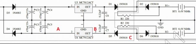
I notice pin 4 is not as low in voltage as pins 3 and 5 in your measurement above. Pin 4 should be at the most negative value as it is the negative supply.
Is pin 4 connected correctly and not floating ? Does it have continuity to point C in my diagram above ?
All my voltages through those points appear fine, I do not have continuity between pin 4 and point C though.
Also you are a legend for helping me out.
Thanks for the kind words
It sounds like your problem is something physical then. You will have to look closely at the PCB and see where the break is. Favourite points would be the pad that the IC socket solders into having a break where the PCB track contacts the pad. A meter check on a low ohms range should soon locate the break hopefully.
It sounds like your problem is something physical then. You will have to look closely at the PCB and see where the break is. Favourite points would be the pad that the IC socket solders into having a break where the PCB track contacts the pad. A meter check on a low ohms range should soon locate the break hopefully.
Thanks for the kind words
It sounds like your problem is something physical then. You will have to look closely at the PCB and see where the break is. Favourite points would be the pad that the IC socket solders into having a break where the PCB track contacts the pad. A meter check on a low ohms range should soon locate the break hopefully.
Any idea what the best path to probe from pin 4 to D6/D5 would be?
- Home
- Amplifiers
- Headphone Systems
- The Objective2 (O2) Headphone Amp DIY Project