Hopefully the noise will be low when it reaches my op amps. I do have intention to put a choke filter at the supplies (or just use inductors). Good thing about SMPS that it's fast to respond to load. The pros for transformer is it does not have switching noise, downside is when loading at low frequency, especially 50Hz. I just have to make sure my design is cater to accept both AC or DC input.
Will use back 4556, each per channel. Does having up to 3 per channel helps?
Will use back 4556, each per channel. Does having up to 3 per channel helps?
Update.
After searching for AC supply wall adapters, it seems to be quite rare nowadays. Especially hard and expensive to get the 230V version. Which lead me to a PCB mount transformer 230VAC to 2 X 6VAC, it also can be configured to accept 115VAC. The casing must also be grounded for safety.
IEC Connector
VTX-121-3023-406 - Isolation Transformer, Encapsulated PCB, 2.3 VA, 2 x 6V, 191 mA, 2 x 115V
As mains supply is not easy to deal with, component selection will have to consider 4mm distance from mains to other traces or metal part.
The PCB will still remain 100 x 100, however the enclosures will now able to house 100 x 160mm PCB.
Hammond 1455N1601
Allied Electronics B3-160BK
The extra 60mm depth will be use to house a rocker switch and an IEC 3 pin switch. They require wiring to the board as it may not have space for the PCB mount version. The downside with a transformer so close to the circuit is may pick up hum.
Honestly, if you're going with a dedicated CT secondary mains xfmr, you might as well do away with the O2's voltage doubler and use higher-voltage secondaries in a conventional +/-15-18V (pre-reg) split power supply instead... like 2x 12 V. The O2's power supply design was a concession to the use of an external single-secondary power transformer (offloading all safety concerns to its manufacturer). Doublers and generally multipliers are always hard on capacitors, you don't use them unless you have to.
I would prefer a different and also smaller 2-pin power connector here (maybe a "figure-8" one?). The 3-pin is ubiquitous but also quite chunky, and building an amp like this as an IEC Class I device generally is the last thing you want unless you fancy ground loop issues. Class II (double insulated throughout) is the way to go. Yes, it has to be built more diligently, but unless you're going balanced, there's no other choice.
I would prefer a different and also smaller 2-pin power connector here (maybe a "figure-8" one?). The 3-pin is ubiquitous but also quite chunky, and building an amp like this as an IEC Class I device generally is the last thing you want unless you fancy ground loop issues. Class II (double insulated throughout) is the way to go. Yes, it has to be built more diligently, but unless you're going balanced, there's no other choice.
Honestly, if you're going with a dedicated CT secondary mains xfmr, you might as well do away with the O2's voltage doubler and use higher-voltage secondaries in a conventional +/-15-18V (pre-reg) split power supply instead... like 2x 12 V. The O2's power supply design was a concession to the use of an external single-secondary power transformer (offloading all safety concerns to its manufacturer). Doublers and generally multipliers are always hard on capacitors, you don't use them unless you have to.
I would prefer a different and also smaller 2-pin power connector here (maybe a "figure-8" one?). The 3-pin is ubiquitous but also quite chunky, and building an amp like this as an IEC Class I device generally is the last thing you want unless you fancy ground loop issues. Class II (double insulated throughout) is the way to go. Yes, it has to be built more diligently, but unless you're going balanced, there's no other choice.
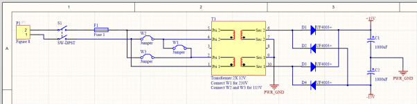
The secondary output is 2 x 6V, which should give me +-15.5Vdc after the diode. If use 2 x 9V I would get +-24Vdc, which would be pretty high for the +-15V regulator. However it's possible if DIYer wanted such configuration, things to take note is the drop in current rating for the same VA rating. Also it's not advisable to use with low impedance cans. I'm not going to do any voltage doubler, just a more simpler objective amp.
https://sg.element14.com/vigortronix/vtx-121-3023-409/2-3va-encaps-transformer-2-x-115v/dp/2817630
One question. Can I use figure 8 ac connector even though I use metal casing? I thought metal casing must always be earth for safety.

The secondary output is 2 x 6V, which should give me +-15.5Vdc after the diode. If use 2 x 9V I would get +-24Vdc, which would be pretty high for the +-15V regulator.
Sorry, wrong math. 2x6V give you about +-8V (6x1,41=8,46), 2x9V give you about +-12V, prfect for opamps.
Sorry, wrong math. 2x6V give you about +-8V (6x1,41=8,46), 2x9V give you about +-12V, prfect for opamps.
Ahh. My bad.
2x9VAC = 12.76 - 1.4 = +-11.36Vdc
2x12VAC = +-15.5Vdc
2x15VAC = +-19.81Vdc
Last edited:
Earlier on I have the intention to build the JRC4556 in -1 gain mode instead of unity gain.
Setup:
Load 15.6 ohm.
-1 gain uses 4.3k ohm in Ri and Rf.
Supply +-9V.
Result:
1mW
Both the same at 0.0027% THD+N
10mW
+1 gain, 0.0012% THD+N, excellent noise less than 2.5uV.
-1 gain, 0.0022% THD+N, noise increase another 6dB compare to +1 gain setup.
Nothing much for me to improve at the output stage. Will investigate the potentiometer next, hopefully no cap or use 10uF elec cap.
Last edited:
Definitely not. There are tons of Hi-Fi devices that are IEC Class II with metal cases. Grab any random Pioneer, Marantz, Sony integrated amp, CD player or receiver, and guess what, chances are it'll have a 2-prong power cord. This is pretty much a necessity when more than exactly one earth connection in the entire system may spell trouble.One question. Can I use figure 8 ac connector even though I use metal casing? I thought metal casing must always be earth for safety.
Now Class II is not the kind of thing a careless and clueless builder could just slap together, so yes, Class I is definitely safer in that regard - everything touchable is on safety earth, so if anything goes wrong internally, it just pops the RCD / GFCI or the fuse. That's why loads and loads of random machinery of all kinds are Class I. As outlined earlier, however, it pretty much isn't an option for classic Hi-Fi applications with their unbalanced connections. I mean, a number of power amps from usually smaller manufacturers are Class I, but those were probably built under the fairly brave assumption that there'd be no external antenna connected to the system. (More recently, I have also spotted some TEAC CD players, even rather fancy ones, built as Class I. That's plain idiocy.)
Honestly I wouldn't be using THD+N when the +N part can be expected to be of the same magnitude as actual THD. (We're not talking DACs here, there are no anharmonic distortion components to be expected.) What if your increase is mostly down to noise? After all, if you do the math, 0.0012% of 10 mW in 16 ohms is just 4.8 µV, barely 6 dB above the noise floor - I would prefer more like 20 dB.10mW
+1 gain, 0.0012% THD+N, excellent noise less than 2.5uV.
-1 gain, 0.0022% THD+N, noise increase another 6dB compare to +1 gain setup.
Granted, in this case I'd expect both noise and distortion to be going up by 6 dB, as distortion suppression driving low-Z loads in the NJM4556 should be limited by spare open-loop gain and your noise gain is up from 1 to 2 (an inverting amp at -1 is after all a noninverting amp at +2 with signal and ground swapped, which is irrelevant for noise). Still, how can you be sure?
If you want to go about tweaking something, direct your attention to the gain stage. Particularly if you have fitted (and require) a high gain option like 6.5X, by all means consider easing up on feedback network resistor values a bit, increasing them by maybe a factor of 2 to 3. (1.5k --> 3.6k or thereabouts if you need 6.5X gain; at 2.5X max gain, going to 2.7k would also do.) The ones originally suggested have the NJM2068 break a bit of a sweat (having to drive an effective 1.5 kOhms while being much happier at >2 and preferably 3+) - feed in 10 kHz at a level approaching input clipping (with an appropriate measurement bandwidth of >40 kHz), and you'll probably see what I mean. (A 19+20 kHz IMD test would be another option if your bandwidth is limited.)
That's a bit of a silly design, after all this stage does not require extremely low noise levels at all - in all likelihood they'll be swamped by signal source output noise anyway. How much does a lil' old Clip+ have, like 6 µV? So do you seriously need 0.5 µV of equivalent input noise then? Won't 0.8-0.9 µV do just fine? Besides, chances are you won't have the volume pot wide open anyway but rather 20 dB or more down most of the time, attenuating input levels to the point where accompanying noise is way below output stage noise.
High input levels are a much more realistic threat. On +/-9 V the 2.5X gain setting won't be able to handle standard CD player levels of 2 Vrms fullscale without running into clipping. Once clipping occurs, there is absolutely nothing you can do on the amp to make it go away, reducing input level is the only option (and may not be possible on a plain CD player).
For a good match to portable players or onboard audio (typically 0.8-1.2 Vrms tops assuming they're unlocked), the 2.5X setting actually isn't bad. Having 1.25X/3X might be a little closer to optimum, but really, the common 1X/2.5X option isn't a terrible compromise at all. The only time you really need a higher gain setting is when trying to accomodate mobile phones and other devices of limited output level in combination with insensitive headphones.
Last edited:
Definitely not. There are tons of Hi-Fi devices that are IEC Class II with metal cases.
Thanks for the long write up. I will look into PCB mount figure 8, dpdt switch and fuse. Hopefully all will be pcb mount to ease assembly.
Spot on. My measurement output cable + 3.5mm connector does produce some noise that raise the noise floor slightly.After all, if you do the math, 0.0012% of 10 mW in 16 ohms is just 4.8 µV, barely 6 dB above the noise floor - I would prefer more like 20 dB.
Since I'm shorting the 4556 output with 2 ohm, not really a great idea to use them in inverse, especially the feedback and input resistor have 1% tolerance. Using in unity gain will have the least mismatch between the 2 op amp, so this design will remain the same.
That datasheet noise is about 1.4uV, at least I'm happy the reading is not too far off.
Yesterday I actually play around with the potentiometer, good news is I can remove the cap as long as the input DC is below 1mV. Noise do increase with the existence of a pot, worst noise when at half resistance. Pot is useful for fix audio signal like CD player. Nowadays I tend to prefer using the volume control in my PC or handphone, for my usage I may not use a pot but I will design in for others who needs it.If you want to go about tweaking something, direct your attention to the gain stage.
I'm thinking a lower supply voltage for low impedance headphone. Putting 30mW into 33 ohm only requires 1Vrms. Which is overkill to have +-12V, reducing to +-9V will make the 4556 happy.
For 600 ohm to get 30mW requires 4.24V, or 12Vpp. If I choose a gain of 3 for the 5532, the Vpp output is 16.97Vpp for a 2Vrms cd player output. Include the +-2V dropout of the 5532 op amp, the ideal supply will be 20.97V. Round up to 21V, dual supply will preferred to be +-10.5V. Where the +-12V will be sufficient.
If the source is 1V, 3x gain still able to output 15mW for 600 ohm. Hence 1X and 3X gain would be a nice choice. As I'm thinking of having low dc offset, the 5532 will be configure in differential mode. But it seems non inverting is not easy to make it differential. Let me think how to configure it.
Honestly the 1 ohms suggested already are quite low already. Doesn't take much of an input offset delta between L and R to get one or more mA flowing (current that's basically wasted, doing nothing but loading the opamps). If in doubt, check what sort of voltage differential you are actually getting (requires a multimeter comfortable with measuring in the single-digit mV range). It may not hurt to have a few 4556s on hand to select manually. Usually their offset delta appears to be low (as expected in a bipolar input part) but there's the occasional bad apple.what would be the lowest possible value to use for R10, R11, R15, R18?
Just manage to learn Altium's component creation for the transformer. Not that hard after watching YouTube tutorial.
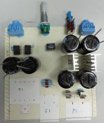
Tomorrow will try paper cut out to see the fitting of the above components.
P1 - Figure 8 AC inlet
https://sg.element14.com/multicomp/jr-201s-pcb/inlet-iec-class2-fig-8-pcb/dp/9248161
S1 - DPST switch
2Pin 3Pin SPST SPDT Car Rocker Boat Switch ON/OFF ON/ON 2 Positions Red Blue Black Green 12V 6A/10A 250V/125VAC 19x13mm Mount -in Switches from Lights & Lighting on Aliexpress.com | Alibaba Group
F1 - Fuse holder and fuse 0.2A
10pcs/lot 5*20mm 5x20mm fuse holder with transparent cover free shipping-in Fuses from Home Improvement on Aliexpress.com | Alibaba Group
5x20mm 250V Glass tube fuse Fuse cutout 0.1A0.2A0.3A0.4A0.5A0.63A0.75A0.8A1A1.5A2A2.5A3A3.15A4A5A6A6.3A7A8A10A12A15A20A25A30A -in Fuses from Home Improvement on Aliexpress.com | Alibaba Group
T1 - 115V/230V to 2X 12V transformer
https://sg.element14.com/vigortronix/vtx-121-3023-412/2-3va-encaps-transformer-2-x-115v/dp/2817631
D1 to D4 - Ultra Fast Diode
https://sg.element14.com/multicomp/uf4003/rectifier-single-1a-200v-do-204al/dp/2675014
Tomorrow will try paper cut out to see the fitting of the above components.
Attachments
According to the paper cut out, all should fit in this case.
YGS 010 106*55 100mm (WxH D) design case box electronic extrusion aluminum metal electrical enclosures-in Connectors from Lights & Lighting on Aliexpress.com | Alibaba Group
Only 90mm width of the PCB is able to use when using the above enclosure.
YGS 010 106*55 100mm (WxH D) design case box electronic extrusion aluminum metal electrical enclosures-in Connectors from Lights & Lighting on Aliexpress.com | Alibaba Group
Only 90mm width of the PCB is able to use when using the above enclosure.
Attachments
Hello guys, I got a question. So my objective 2 worked perfectly for about 4 years now, but a day or two ago it just stopped lighting the red LED while connected to the ac power supply. I've measured the power supply and it reads the correct voltage, which means the power adapter shouldn't be what went wrong.
So I'd like to know what would be the next troubleshooting I could do to figure out what is wrong.
Thanks in advance
So I'd like to know what would be the next troubleshooting I could do to figure out what is wrong.
Thanks in advance
Have you checked the -/+ 12 v DC supplies are correct ?
Follow post #3775 if you get stuck and see where yours fails.
The Objective2 (O2) Headphone Amp DIY Project
Follow post #3775 if you get stuck and see where yours fails.
The Objective2 (O2) Headphone Amp DIY Project
9 volts suggests a problem.
You need to confirm that you have at least PLUS 15 volts entering the 7812 regulator and MINUS 15 entering the 7912 regulator. The output from each regulator should be +12 and -12 respectively.
If either regulator is hot then something could be drawing to much current and pulling the voltage down.
If the regulator is cool and you have 15 volts or more entering it then it does suggest a problem with the reg.
Do make sure that there is continuity from the reg through D1 and through the switch though. D1 should have no more than around 0.7 volts across it when forward biased. e.g if you have your 9 volts on the anode (that goes to the reg) then the other end should be at no less than around 8.3 volts. Vice versa for the negative regulator i.e no more than 0.7v across D5.
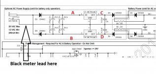
Like this. The black meter lead goes on the main ground connection that runs throughout the amp.
Point A should be > +15 volts DC
Point B should be > - 15 volts DC
Point C should be approx +12 volts DC
Point D should be approx - 12 volts DC
Thank you very much.
So I got +11.1V DC on point C and -11.7V on point D.
On the points after that (the opamps 1 and 8) I got 10.5V on the positive point and -11.1V on the negative. What would be your suggestion (since it is lower than 12V)
- Home
- Amplifiers
- Headphone Systems
- The Objective2 (O2) Headphone Amp DIY Project