It takes a few minutes to pop out the 1688s and insert the 4456's back in, but I did this as well this am and my immediate impression was the 1688's are better then the 4556's. I played a well known demo cd with extreme bass stuff and it really popped and amazed me. But again it may be my brain just playing around again. But there is no hesitation leaving in the 1688's with the headphones I am using...I only used the my 35 ohm MSR7s this am for listening.
Alex
Alex
Hey guys I got this question over at another forum:
I really like your mod, but I'm worried about how the OPA1688 will handle output power under 32 ohms or even lower impedance headphones, because despite having the same mA output I see from the datasheet that can only handle 50mW/32ohms before clipping; for 2 paralleled opamp this would be 100mW/32ohms, so about 6 times less power than original 4556 opamps (please correct me if I'm wrong).
I will most likely purchase a couple of OPA1688 opamps soon, because I'm very interested in final results, but meanwhile do you think you could please test output power of your modded O2 with OPA1688 as output buffer for 32ohms output resistance? Also, if you could somehow measure OPA1688 die temperature while doing this test it would be perfect.
I only have used my 250 ohm T90's so far, I will try with lower impedance headphones and a thermocouple today.
Ideas??
Alex
Remember that power is current squared times resistance. The OPA1688 clips into 32 ohm loads when it hits its internal current limiting circuitry. 1 channel of an OPA1688 (1/2 the chip) will deliver 50mW into a 32 ohm load without clipping, which is about 40mArms. If you put both channels on the chip in parallel, the output current available doubles to 80mArms, which is ~205mW. 2 OPA1688 chips, with all 4 amplifiers in parallel would be 40mArms x 4 = 160mArms or 819.2mW.
Thanks John!
I appreciate the information, I have built several of AGDR's SuperCmoy's and they all play very well. I never have an issue with power to drive my headphones, 35ohm to 250ohm.
Its good to see TI making chips and ICs for our small part of the world. I wonder if any of the 'big' oems or vendors are using these in future designs?
Alex
[...] 2 OPA1688 chips, with all 4 amplifiers in parallel would be 40mArms x 4 = 160mArms or 819.2mW.
Thanks a lot John!
As there are 2 amplifiers per opamp, that would be 819.2mW/channel, right?
Thanks a lot John!
As there are 2 amplifiers per opamp, that would be 819.2mW/channel, right?
How many OPA1688s are you using per channel of the headphone amplifier? If it matches the original O2 schematic, which used 1 NJM4556 per channel with both internal amplifiers in parallel. Then it is the second case that I listed above, 2 * 40mArms = 80mArms. ( 80mArms^2 ) * 32 ohms is 205mW.
I should also point out that the 50mW per amplifier of an OPA1688 figure is before any onset of clipping (THD+N = -109.5 dB / 0.000335% ) which is quite a bit different than where the 534mW/channel measurement I see for the O2, which is taken at 1% THD+N.
I'm not sure where you're getting the 534 mW from, NwAvGuy's original article shows 613 mW @1% into 33 ohms, plus 0.002% THD+N at 190 mW. Onset of clipping is at about 4.3 Vrms (or ~560 mW) / 0.0035%.
Of course, 50 mW is going to be easily sufficient for any headphone of about 93 dB / mW or higher.
Of course, 50 mW is going to be easily sufficient for any headphone of about 93 dB / mW or higher.
I'm not sure where you're getting the 534 mW from, NwAvGuy's original article shows 613 mW @1% into 33 ohms, plus 0.002% THD+N at 190 mW. Onset of clipping is at about 4.3 Vrms (or ~560 mW) / 0.0035%.
Of course, 50 mW is going to be easily sufficient for any headphone of about 93 dB / mW or higher.
I got it from this graph on the O2 summary page
An externally hosted image should be here but it was not working when we last tested it.
But I do see the other measurements on the O2 measurements page. Since the onset of clipping is a step even, differences in measured output power can often just be from a different number of data points in the measurement.
Hi,
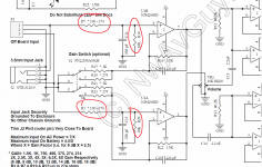
do i understand it right, that the input impedane of the O2 is solely determined by R14/R20 (10K) in parallel with the input impedance of the opamp(JRC2068)?
And that R14/R20 could also be used to compensate for DC-offset, but since there is no fixed gain, and the next stage is AC-coupled anyways it doesn't matter here right?
I'm asking because(other than learning more") ) i want a higher input impedance, so that the passive "meier enhanced bass crossfeed" which i integrated into the O2 works like the inventor intended it.
) i want a higher input impedance, so that the passive "meier enhanced bass crossfeed" which i integrated into the O2 works like the inventor intended it.
With 10K input impedance it's everything but "bass enhanced", and the crossfeed level and delay are off too, so i botched another JRC4556 as output buffer for the x-feed into my O2, which works great(after i actually added 47K resistors from the non-inverting inputs to ground - before there was a pop every time i switched - DC-offset related i guess).
Couldn't i just have replaced R14/R20 from 10k to like 100k and be done(with even better performance of the x-feed)?
If my assumptions considering input impedance are right, then why does the O2 only have 10K?
Less noise?
Wouldn't less load on the source outweigh this?
Another related thing:
R3/R7 (100ohm i guess) must be added to the output impedance of the source, to get the total output impedance seen by the O2 right?
do i understand it right, that the input impedane of the O2 is solely determined by R14/R20 (10K) in parallel with the input impedance of the opamp(JRC2068)?
And that R14/R20 could also be used to compensate for DC-offset, but since there is no fixed gain, and the next stage is AC-coupled anyways it doesn't matter here right?
I'm asking because(other than learning more
) i want a higher input impedance, so that the passive "meier enhanced bass crossfeed" which i integrated into the O2 works like the inventor intended it.With 10K input impedance it's everything but "bass enhanced", and the crossfeed level and delay are off too, so i botched another JRC4556 as output buffer for the x-feed into my O2, which works great(after i actually added 47K resistors from the non-inverting inputs to ground - before there was a pop every time i switched - DC-offset related i guess).
Couldn't i just have replaced R14/R20 from 10k to like 100k and be done(with even better performance of the x-feed)?
If my assumptions considering input impedance are right, then why does the O2 only have 10K?
Less noise?
Wouldn't less load on the source outweigh this?
Another related thing:
R3/R7 (100ohm i guess) must be added to the output impedance of the source, to get the total output impedance seen by the O2 right?
Attachments
...do i understand it right, that the input impedane of the O2 is solely determined by R14/R20 (10K) in parallel with the input impedance of the opamp(JRC2068)?
I think you got it. The input impedance of an ideal opamp is infinite, but in the real world is actually more like 100K and up, depending. You can certainly increase that to any value you want by changing R14/R20. It will alter the dc offset of the opamp, but as you note it's AC coupled so it does not matter. I have read somewhere that the "standard" impedance for consumer stereo stuff is 20K, but I've not actually seen the standard. If it works for you, it's the right answer.
Pretty much as mlackey says although the intrinsic input impedance of the opamp doesn't really figure in the equation as its 'extremely high'. Hard to put a figure on it as it depends on the exact device and the feedback wrapped around it but typically you are looking at around 10 meg ohm.
If the output voltage of this meier stage is at nominally zero volts then you can direct couple that to the O2 input and remove R14 and R20 because the preceding stage will set the DC operating points of the 02 stage. If the output is not zero then you need to AC couple (0.22 or 0.47uf) and raise R14 and R20 to around 470k.
If the output voltage of this meier stage is at nominally zero volts then you can direct couple that to the O2 input and remove R14 and R20 because the preceding stage will set the DC operating points of the 02 stage. If the output is not zero then you need to AC couple (0.22 or 0.47uf) and raise R14 and R20 to around 470k.
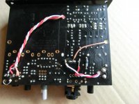
yea, that is a good idea to AC-couple the buffer opamp, because then i wouldn't need the bias resistors, and had only the input impedance of the opamp seen by the x-feed circuit(like i wrote, i left the bias resistors out at first, but didn't AC-couple then, so it produced pops whenever i switched the x-feed, and between xf-levels).
On the other hand, if i decided that 47K input impedance would be right for the x-feed, i could just change R14/R20 to 47K, and rip the buffer opamp out again.
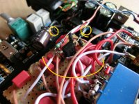
BTW: that's from where i power the opamp, probably all bad for measurement performance.
On the other hand, if i decided that 47K input impedance would be right for the x-feed, i could just change R14/R20 to 47K, and rip the buffer opamp out again.
BTW: that's from where i power the opamp, probably all bad for measurement performance.
Attachments
Last edited:
ah, i will think over all this a night.
@thermal runway
Head 'n' HiFi - Walter
(from switzerland)
I bought my kit from there too.
With the desktop version upgrade parts + power supply it was ~75€ incl. shipping.
edit: oh, looks like he deleted the post again.
@thermal runway
Head 'n' HiFi - Walter
(from switzerland)
I bought my kit from there too.
With the desktop version upgrade parts + power supply it was ~75€ incl. shipping.
edit: oh, looks like he deleted the post again.
Last edited:
Power issues and LED does not turn on
Hello,
This post is a bit long. But, I included all measurements I did from the testing and troubleshooting sections.
I just built a new Objective2. But, the LED does not turn on when I connect the AC adapter and turn the power on.
Initial Testing
These initial steps follow NwAvGuy: O2 Details.
Resistances
I am planning to use this with an ODAC, so I cut the J2 traces. This leads the resistance of R14 and R20 to be ~10K, rather than 100-300. The 1 Ohm resistor differences are caused by my DMM. Here are all of the resistance measurements with U2 in, power on, and no power:
I put a * next to questionable measurements. R6 should be 40 K, R25 should be ~330 K, and R1/R2 should be 100 - 220. I don't think these differences would cause the LED to not light.
AC Wall Transformer
I measured the wall transformer as 18 ACV.
Supply Voltages
With power connected and the power switch off, I measured from BT1+ to BT2- as 23.4 V.
With power connected ans the power switch on, the voltage dropped to 23.2 V. However, the LED does not light. So, I moved on to the troubleshooting section: NwAvGuy: O2 Details.
Troublshooting
Top 5 Issues
Step-By-Step DC Voltages
U2 is not installed at this point. Power is off and the amp is plugged in.
At this point, I'm fairly confident I fried U2. But, that doesn't explain why the LED doesn't light when U2 is out. I measured the voltage at the LED (with the usual ground), and it changed when the power switch changed. Could the resistance differences cause this?
Thank you for any help!
Hello,
This post is a bit long. But, I included all measurements I did from the testing and troubleshooting sections.
I just built a new Objective2. But, the LED does not turn on when I connect the AC adapter and turn the power on.
Initial Testing
These initial steps follow NwAvGuy: O2 Details.
Resistances
I am planning to use this with an ODAC, so I cut the J2 traces. This leads the resistance of R14 and R20 to be ~10K, rather than 100-300. The 1 Ohm resistor differences are caused by my DMM. Here are all of the resistance measurements with U2 in, power on, and no power:
Code:
 R7 | 271
 R3 | 271
R14 | 9.8 K
R20 | 9.8 K
R22 | 1288
R16 | 1284
R12 | 39.9 K
R13 | 39.9 K
 R6 | 39.1 K*
R10 | 1.5
R11 | 1.6
R18 | 1.4
R15 | 1.5
 R5 | 97.6 K
 R9 | 310 K*
 R8 | 228 K
 R4 | 266 K
R24 | 266 K
 R2 | 236*
 R1 | 236*
I put a * next to questionable measurements. R6 should be 40 K, R25 should be ~330 K, and R1/R2 should be 100 - 220. I don't think these differences would cause the LED to not light.
AC Wall Transformer
I measured the wall transformer as 18 ACV.
Supply Voltages
With power connected and the power switch off, I measured from BT1+ to BT2- as 23.4 V.
With power connected ans the power switch on, the voltage dropped to 23.2 V. However, the LED does not light. So, I moved on to the troubleshooting section: NwAvGuy: O2 Details.
Troublshooting
Top 5 Issues
- I don't see any obvious soldering issues. I checked for shorts on the power switch, but it matches the datasheet.
- Components are in the right direction. I didn't install battery terminals since this will be AC only.
- I triple checked component locations and the wall transformer is 18 ACV.
- It's possible I damaged Q1 and/or Q2. I did not use a static mat or wrist strap.
- I omitted the battery terminals and cut the traces, but everything else is standard.
Step-By-Step DC Voltages
U2 is not installed at this point. Power is off and the amp is plugged in.
- The problem is the LED not turning on.
- Nothing is getting hot.
- Negative Unregulated Supply. Unbanded end of D4: -25.2 V.
- Positive Unregulated Supply. Banded end of D3: 25.2 V.
- Balanced Power. 3 and 4 match.
- Regulated Positive Supply. Unbanded end of D1: 11.8 V.
- Regulated Negative Supply. Banded end of D5: -11.8 V. The goal is -12 V (within range).
- Power Switch. I unplugged, installed U2, plugged in, double checked steps 3-7, and turned the switch on. During one test, I installed U2 the wrong direction, turned the power on, smelled something wrong, unplugged, then fixed U2. I saw the LED turn on for a few seconds at some point here. So, I'm not sure if U2 is damaged. Steps 3-7 were the same.
- Positive Battery Voltage. BT1+ was 11.6 V. I used the center terminal of the + side of BT1.
- Negative Battery Voltage. BT2- was -11.6 V. I used the center terminal of the - side of BT2.
- U2 Pin 2: Voltage was -8.8 V. This is a bit far from the guide of -8.4 V. So, I checked the other numbers:
- R5 closest to the batteries was 11.6 V (within range of the guide of 11.8 V).
- R9 away from the batteries was between -11.5 V and -11.6 V. So, this is probably OK. The goal is -11.8 V.
- I checked R5 and R6 are the correct resistors.
- U2 is the right part (2903), in the right way, and in the right location. But, may be damaged from a previous attempt.
- U2 Pin 3: Voltage was positive 9.5 V. The LED is not on.
- R6 at the edge of the board is also +9.5 V. The other end is +11.6 V, not -11.8 V.
At this point, I'm fairly confident I fried U2. But, that doesn't explain why the LED doesn't light when U2 is out. I measured the voltage at the LED (with the usual ground), and it changed when the power switch changed. Could the resistance differences cause this?
Thank you for any help!
Thank you for the quick response and link! Here are the numbers from that guide.
U1 - U4 are all out. S1 is off. No batteries.
Unregulated Power
From the guide this indicates a problem around U2 and the FET rail switches.
So, I disconnected power, left S1 on for a bit, then uninstalled U2.
Is there a way to check if U2, Q1, and Q2 are working?
U1 - U4 are all out. S1 is off. No batteries.
Unregulated Power
-
 Striped end of D3: 25.2 V.
 - Non striped end of D4: -25.3 V.
- Striped end of D1: 11.7 V.
- Non striped end of D5: -11.7 V.
- I disconnected power, turned S1 on, waited 1 minute, then installed U2.
- Opamp measurements. The longer I measure, the more the measurements increase (negative values get closer to 0). So, these numbers are the last ones I saw. The guide says these should be -11.5 - -12 for pin 4 and 11.5 - 12 for pin 8.
- U1. Pin 4: -.45 V. Pin 8: -.62 V.
- U2. Installed.
- U3. Pin 4: -.44 V. Pin 8: -.61 V.
- U4. Pin 4. -.44 V. Pin 8: -.61 V.
From the guide this indicates a problem around U2 and the FET rail switches.
So, I disconnected power, left S1 on for a bit, then uninstalled U2.
Is there a way to check if U2, Q1, and Q2 are working?
Although U2 is suspect, we still always check the basics. Just confirm that U2 has the correct supply on pins 4 and 8.
So that's your -11.7 on pin 4 and plus 11.7 on pin 8.
Assuming that is correct can you measure and record the voltages on the other 6 pins of U2.
Yes we can determine what's going on and check the FET's if needed.
Copy and paste this with the results.
Pin 1=
Pin 2=
Pin 3=
Pin 4=
Pin 5=
Pin 6=
Pin 7=
Pin 8=
- Home
- Amplifiers
- Headphone Systems
- The Objective2 (O2) Headphone Amp DIY Project