Hello
I would like to comment something about this amp (I have the first version). I´ve been working this weekend on the DC offset and I´ve noticed some details about it :
1º I changed the original trimpot for a 20 turning trimpot.
2º I added a pair of bipolar Caps (1000 uF) on the output.
Well, on the first moment (when it started) I checked 150 mVolt on L and R channels. Immediately the voltage lows. After 10 minutes the voltage stabilizes at +5 / -5 mVolts and it keeps on this range, but it depends majoritily on ambient temperature. In a closed box is very difficult to leave the offset on these values. I think that it's the big problem of this amp and I thing that add a canceller DC offset circuit it´s the best solution.
Although military grade components or boutique are not used, the sound is pretty good but certainly it does not sounds like a "giant killer" (I have a Beta 22 and Bijou which are clearly much higher)
Personally I like to compare this amp with my clone RA1 (with Solen and PSU). I prefer the greater warmth of the JLH, but to try to regulate the Offset is certainly a handicap.
Regards
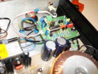
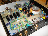
Hello
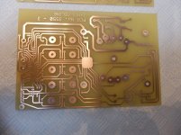
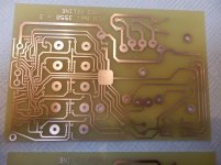
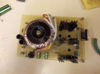
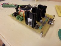
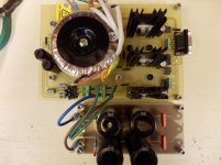
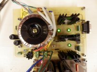
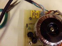
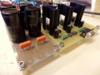
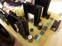
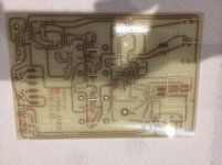
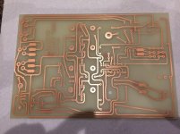
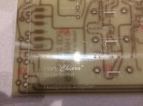
I am making another JLH headphone amplifier .. this time with a new improved power supply. I am using my new 2oZ copper track PCB with a off board capacitor bank for easier upgrading at a latter date .. so just a few pics
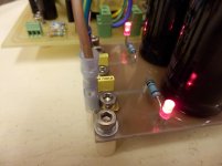
The mains lead is just for testing . .some learning's I think 18 v sec is to hign as this gives 28v before the regulators, 15 v ac sec would have been better as they give just above 20v dc before the regulators which would be fine. Plus the 1k led resistors on the capacitor bank need increasing in wattage as they get a little to hot
I have also added some voltage rail LEDS just for quick visual check reference and a little loading ..
I am making another JLH headphone amplifier .. this time with a new improved power supply. I am using my new 2oZ copper track PCB with a off board capacitor bank for easier upgrading at a latter date .. so just a few pics
The mains lead is just for testing . .some learning's I think 18 v sec is to hign as this gives 28v before the regulators, 15 v ac sec would have been better as they give just above 20v dc before the regulators which would be fine. Plus the 1k led resistors on the capacitor bank need increasing in wattage as they get a little to hot
I have also added some voltage rail LEDS just for quick visual check reference and a little loading ..
Attachments
-
 P8190016.jpg360.2 KB · Views: 647
 -
 P8190015.jpg388.6 KB · Views: 639
 -
 P8190018.jpg297.5 KB · Views: 620
 -
 P8190019.jpg282.9 KB · Views: 586
 -
 P8220023.jpg369.7 KB · Views: 560
 -
 P8220024.jpg336.4 KB · Views: 220
 -
 P8220025.jpg297.5 KB · Views: 165
 -
 P8220026.jpg235.8 KB · Views: 167
 -
 P8220021.jpg303.7 KB · Views: 235
 -
 P8220022.jpg307.8 KB · Views: 191
Last edited:
Hello .. depends on what I am using the power supply for, sometimes +/- 12v or +/- 15v then I use a 3rd regulator normally 5v or 12v to feed aux remote volume control PCB for example.
Its a simple board but I like it and can be modded very well and space to work on the PCB .. but thanks for the interest
Its a simple board but I like it and can be modded very well and space to work on the PCB .. but thanks for the interest
James,no thoughts then ?
can you attach the pics missing from post1?
I just put it in a wooden box with a toroidal trafo and RCA inputs. Still waiting for 1/4in stereo jack to install. In meantime I had a listen with temporary 3.5mm jack on MDRV6's. Wow the sound is incredible. Deep deep bass and soaring clear highs.
Needed the box to use this at work. Most of my projects don't have a real box - I found that little craft boxes like this are convenient and inexpensive. This one was $5 from Michaels.
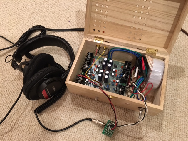
Needed the box to use this at work. Most of my projects don't have a real box - I found that little craft boxes like this are convenient and inexpensive. This one was $5 from Michaels.
This little amp works like a charm - well beyond the $20 cost of the board, $11 for toroidal transformer, $5 for misc RCA input and TRS stereo out jack. Btw, I am using the GLS Audio 1/4in stereo TRS jacks and they are really nice. All metal high quality with a decisive click. They look bullet proof and will last forever.
One issue I have and I think it's because I don't have the main board connected to earth ground is that when the volume pot is not on full output there is hum. So I need to fix that (also for safety).
Sound wise it's a fantastic amp and I am looking forward to trying some better headphones than my 20yr old Sony's on them.
I am thinking of building my own headphones with a nice Visaton B80 full range driver. Will 3D print the yoke and headband. Ordered some foam cushioned earpads alread. There is a thread for that in Fullrange forum.
If it's all enclosed and there are no metal/conductive parts to touch, then Safety is much less of an issue. Just use a close rated fuse. Make sure any equipment you connect it to, also has a close rated fuse...................One issue I have and I think it's because I don't have the main board connected to earth ground is that when the volume pot is not on full output there is hum. So I need to fix that (also for safety). .......................
Try to use twisted pairs for more of your wiring.
Connect any non-audio internal metal work to a common ground reference.
James,
can you attach the pics missing from post1?
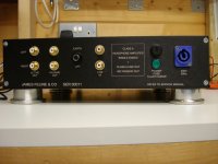
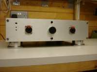
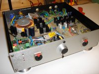
Hello sorry for the delay .. please find a few pics from the 1st posts .. this unit has long gone to a happy owner
Attachments
-
 Camera back up pics (128).JPG529.7 KB · Views: 217
 -
 Camera back up pics (126).JPG528 KB · Views: 214
 -
 Camera back up pics (123).JPG577.3 KB · Views: 386
 -
 Camera back up pics (122).JPG596.6 KB · Views: 397
 -
 Camera back up pics (121).JPG533.6 KB · Views: 410
 -
 Camera back up pics (120).JPG541.3 KB · Views: 412
- Home
- Amplifiers
- Headphone Systems
- JLH Class A headphone amplifier