Hi
I have just ordered one of these JHL amps from the same ebay source.
After reading this I'm a bit concerned. do I need to make this servo before using with my nice headphones and if so could it be explained in simpler terms. I'm pretty good with a soldering iron but have little or know knowledge of electronics.
Hi,
the output cap blocks the DC bias that is on the output of a single polarity supplied amplifier.
It does not need to be bi-polar, a polarised electrolytic will do and with the bias voltage will operate better than an unbiased electrolytic at passing the audio signal.
If you increase the output offset from 0.1V to let's guess, 0.5V the electro will perform reasonably well.
Use this as a temporary/experimental measure and listen to it.
If you decide to try the DC servo, you can listen and research at the same time ready for the small modification that is required to add the servo to the circuit.

Hi,
the cap value determines the LF response of the amp/speaker combination.
Use C=1/[2 * Pi * Rload * Freq]
Aim for freq lower than 10Hz and Rload = headphone impedance in ohms.
C will come out in Farads. Multiply your Farads answer by 1million (10^6) to get a microFarad (uF) value. 16V or 25V should do for headphone use.
so that comes out at approx 420uF for 38ohm and 10Hz
and 840uF at 5Hz,
So I should go for something around 500uF that would bring me in just under 10Hz
did I do that right?
Thanks again I really appreciate you guys taking the time to help.
If someone would like to explain how this works I'd love to know.
and 840uF at 5Hz,
So I should go for something around 500uF that would bring me in just under 10Hz
did I do that right?
Thanks again I really appreciate you guys taking the time to help.
If someone would like to explain how this works I'd love to know.
Hi,
the caps usually come in E6 values: 1, 1.5, 2.2, 3.3, 4.7, 6.8 and decade thereafter.
You could use a 470uF or 680uf or 1000uF. I would be tempted to try both 470uF and 2200uF to hear if there is any difference. They will both be very cheap.
Once you know that you like or dislike listening through the capacitor you can decide whether you want to try a high quality Audio Electrolytic that could be anywhere from twice as expensive to ten times as expensive or go the servo route.
The capacitor is wired in series between the amplifier output and the output socket for the headphone. One cap to each channel.
Read what's on thi sthread to get additional info on JLH headphone amps
Check out this thread.
http://www.diyaudio.com/forums/headphones/159202-jlh-headphone-amp.html
I tried both single supply with output capacitor ( potentially fail safe ) and the split supply without output capacitor. Both sound very good and I didn't find the offset anything to complain about. It was very low.
Cheers.
capacitors
Hi guys, my knowledge of electronics is very poor L
I’m surprised me with this problem. I recently bought a JHL amp from the same source on E-bay in order to use it with my Grado SR60i (32ohm).
I see that the use of JHL amplifier is not recommended without building servo. I'm not so skillful to make a servo but I could try with two ELNA SILMIC II 25V 1000UF Capacitors or something like this.
Im just not shure if I understood right? I should use capacitors like:
- 470uF or 1000uF or 680uf or 2200UF. ?????
- 16V or 25V ?????
- integrate capacitors between the outputs on the amplifier and headphone jack (one for L and one for R)?(from amp thru cap to headphone?)
Has anyone tried this already? How does that sound?
Thanks
</SPAN>
</SPAN>
Hi guys, my knowledge of electronics is very poor L
I’m surprised me with this problem. I recently bought a JHL amp from the same source on E-bay in order to use it with my Grado SR60i (32ohm).
I see that the use of JHL amplifier is not recommended without building servo. I'm not so skillful to make a servo but I could try with two ELNA SILMIC II 25V 1000UF Capacitors or something like this.
Im just not shure if I understood right? I should use capacitors like:
- 470uF or 1000uF or 680uf or 2200UF. ?????
- 16V or 25V ?????
- integrate capacitors between the outputs on the amplifier and headphone jack (one for L and one for R)?
(from amp thru cap to headphone?)
Has anyone tried this already?
Thanks
</SPAN></SPAN>
.....Im just not shure if I understood right? I should use capacitors like:
- 470uF or 1000uF or 680uf or 2200UF. ?????.......
Depends on your headphone impedance and what you want your low frequency turnover to be ( -3dB ) .
C= 1/( 2*pi*f*Z)
F is the -3dB frequency and Z is the headphone impedance in ohms.
So for a 60 ohm headphone and a -3dB at 20 Hz , C = 133uF.
For a bipolar capacitor you use two capacitors in series and so each capacitor should have twice this capacitance = 266uF.
So a 220uF standard value is just about Ok . Or you could use a higher value possibly 470uF which is easily available. F -3dB will now be 11Hz.
- 16V or 25V ?????.....
Depends on your dc supply to the circuit. Capacitor voltage rating should be equal to or higher than the supply voltage. So +/-12 V dc supply can use 16 V caps. +/-18 V supply will need 25 V caps....and so on !
- integrate capacitors between the outputs on the amplifier and headphone jack (one for L and one for R)?
(from amp thru cap to headphone?)........
Yes ! Connect the minus terminals of the caps together, One plus terminal goes to the amp and the other plus terminal goes to the headphone + ve terminal of one channel. - ve terminal of the two channels is usually connected together and is the ground terminal.
Separate capacitors for each channel. So you need 4 capacitors totally.
Last edited:
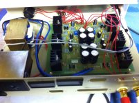
Some pics, its standard so far I wanted to get it working before I start messing with it. Setting the dc offset was quiet fiddly; it sounds excellent but its my first so don't have anything other than nothing to compare it with.
Attachments
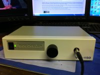
Heliguy, That looks excellent. Yes it's a very good headphone amp , you needn't have to compare it with anything else.
I recently had an urge to get a headphone which had very good reports by many guys on the Net. Many claimed it was incredibly priced. So I bought it for US$48 from Amazon. Audio technica ATH-M30.
It is VERY good ! I have a Sennheiser HD580 and many other phones from Philips, Audio technica and Sony and other Sennheisers. But this one is worth every penny. Get it before demand goes up and prices escalate.
Is this the best headphone ? There never will be such a thing. It's musical, great bass and nice 'taut' bass , wonderful midrange and sweet highs. Not the best fit but good enough for reasonably long listening sessions without discomfort. It light and it's impedance is fairly flat I think. That will make it quite immune to a large headphone output impedance. With the JLH that isn't any problem.
Cheers.
I never found any fiddly problems setting the offset. Wonder why you had a problem. In any case if you use a bipolar output cap it doesn't matter at all.
Ok I suppose it was to be expected but After more considered listening there an awful background hum; its not there or at least not noticeable at lower volumes but quiet irritating once I start turning it up a bit.
Should I tie the output ground to the chassis?
Should I ground the zero volts?
Would either of these help or should I be looking elsewhere.
Would a toroidal transformer help?
Would ferrite cores help?
Should I tie the output ground to the chassis?
Should I ground the zero volts?
Would either of these help or should I be looking elsewhere.
Would a toroidal transformer help?
Would ferrite cores help?
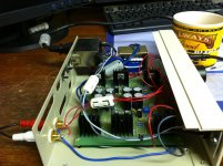
ok the ferrite cores made little or know difference, but grounding the input made all the diff in the world, there is still a slight hiss any suggestions?
Also its input is an iphone; When its connected to the pc (iphone) there is horrible interference. Disconnect from pc and it gone obvious solution is not to sync while connected to the amp but it would be nice to charge it while listening, any idea's
Also its input is an iphone; When its connected to the pc (iphone) there is horrible interference. Disconnect from pc and it gone obvious solution is not to sync while connected to the amp but it would be nice to charge it while listening, any idea's
Attachments
Last edited:
Lets try to fix your issues.
The ferrites will not solve your problem. You should remove them because they add no value in your situation - your problems are elsewhere as outlined below.
1. It looks like you are using non screened wiring to connect your volume control to the circuit board. I'd use some screened wire here - so inner two wires would be signal, and the screen the ground side of the pot. Reason: the pot wiper is a high source resistance, and therefore susceptable to a lot of noise pick-up via capacitive coupling.
2. You potentiomenter housing should have a good connection to ground - this should happen in any event because of the way the pot is mounted on the front panel. However, double check that your potentiometer shaft to chassis is open circuit. Highly unlikely, but just check it anyway.The pot housing acts as a screen, and prevents capacitive coupling onto the pot track.
3. Your cabling from the transformer onto the PCB - twist the wires tightly together so you minimize the area between the wires - this will reduce radiated noise (50/60Hz and harmonics). The way it s hooked up now means all this gunk is coupling into the volume pot wires and the PCB tracks.
4. Your headphone socket. Same story, twist the ground and L and R channels wires tightly together. Keep this bunch of cables well away from your pot cables and the transformer cables.
5. Use a meter and check carefull that your headphone socket is NOT electrically connected to the chassis other than via the headphone ground return wire to the PCB. To do this, unsolder the wires to the headphone socket and measure the socket ground to chassis - it should be open circuit. If you have a short, or low Ohms reading, you have a ground loop, and this will give you noise and hum.
6. Check that your input sockets are not connected to the chassis other than via the screen on the socket to PCB wiring.
7. You must have only 1 connection from your circuit board to the chassis. This must run from the junction of the filter capacitors to a secure point on the chassis. The incomming earth from the AC line receptacle must also be connected to the chassis. If there is any other path to the chassis other than via the single wire from the junction of the filter capacitors, it willl create an earth loop, and you will get hum and noise. Further, if you are anywhere near a PC or SMPS adaptor powered devices, the radiated noise from that adaptor wilol couple into your amplifier causing hum, hash and a lot of HF noise. Terrible stuff.
8. Final points: Keep the potentiometer wiring well way from the headphone and transformer wires. Keep the transformer wiring well away from the headphone and potentiomer wiring. Twist the wiring tightly as mentioned above.
Follow these simple rules and its quite easy to build audio stuff that is as quiet as good commercial equipment - so down at -100 to -120dB.
Lets tackle the problem you have when you plug into your PC after you have sorted the above problems out - I suspect however if you do 1-8 above, your problem will be solved.
Someone else also had the hiss problem. He found that it actually came from his iPod equivalent source.
Short the inputs to ground and see if you get hiss. If you don't then thhe hiss is coming from the source. If there is a digital control for volume on the source the output circuit in it is going full blast and chance of audible hiss is very high.
If all else is fine and the hiss is always there, you might be having some HF oscillation. You can try a larger compensating capacitor. Try 50% more, then double its value an dthen triple. But doing that could kill the slew rate and affect the quality of the sound. It would b eideal if you get to see the output on a scope. It should tell all.
Dear all,
With respect to the ebay JLH amp. I had no problems with hum initially as I evaluated it powered by two car lead acid batteries.
I then wired up a transformer without testing so it ended up the wrong way and destroyed the power regulation capacitors. 25 V to 15 V is a lower tolerance than I would have done in my own design. I then replaced the power regulation input capacitors and bought a second ebay amp.
I then decided to power it from my preamp power supply of +-15V regulated. This solved most of the HUM issue.
I then found an old box of biscuits tin and put it in with an earth connection and finally the HUM was gone.
With the new amp I still have some high frequency noises, that sound like an old AM radio, so I guess I have some oscillation issues with it. I have to try my fixed version and see if that has the same issue, as I never noticed it before with the batteries powering the amp.
I will get back to you all with some scope measurements some time.
Regards
Owen
- Home
- Amplifiers
- Headphone Systems
- JLH Class A headphone amplifier