Mooly. very interesting ...but the point is how about sound impression? thx
Hi ferynov... listening impressions are good, very good. It's incredibly detailed, with no sense of harshness or dynamic compression that seems to creep in with the usual opamp offerings.
an inexpert question.. what makes the germaniums in class A that prevents to use heatsinks?
It doesn't need heatsinks because the power dissipated in the output stage is low and well within the ratings of the transistors used in free space.
Member
Joined 2009
Paid Member
Mooly,
Reading your thread at 2am in the morning this week I got all nostalgic about some black painted OC devices I used to have when I was a kid. Never did anything with them and no longer have them.
But it was early in the morning, my brain was a bit over-taxed and somehow I found myself on ebay. I don't know how or why but for some reason there is a pack of qty 10 of OC71's coming to me in the post. They don't even look suitable for a project, I think they are limited to very low current such as 10mA. But they are black and look like what I remember. Perhaps they are useless.
What shall I do !
That's a cool project. I've got a handful of AC125, AC128 and OC81, it would be interesting to make something useful with this stuff. What can be possible replacement for Q1 except ACY21?
Out of what I had, the ACY21 worked the best... it's all so non critical though.
Try what you have, and just make sure the bias is optimal.
The AC125 or 128 will work, but the HF response was a bit better with the ACY21.
It's a different approach to using silicon where you know that leakage is zero and that the devices are consistent.
I tried to design this amp so most devices would work, that's one reason the resistor values are low, to swamp out device differences.
I would have the NPN device was more of a problem to find.
don't know how or why but for some reason there is a pack of qty 10 of OC71's coming to me in the post. They don't even look suitable for a project, I think they are limited to very low current such as 10mA. But they are black and look like what I remember. Perhaps they are useless.
What shall I do !
10 ma sounds about right for the OC71.... I'd have to dig the old data books out to check. You would have to try them. If they are the really old ones you can scrape the paint off and use them as phototransistors (OCP71's) but later ones stopped you doing this by using opaque "jelly" in the device rather than clear.
I just found this while searching the OC81,
AMZ Germanium Transistor Buffer
this uses much higher value resistors, particularly for the bias network. I tried that approach but found it to dependant on each device (the leakage is so variable). I ended up with 47k and 100 bias which gave symetrical clipping on that stage... at odds with designing theoretically... but it's what works for the germaniums.
Experiment and have a play... if you haven't a scope use a DVM and set the bias to give 1/2 vcc at the emitter of Q1.
Last edited:
Member
Joined 2009
Paid Member
10 ma sounds about right for the OC71.... I'd have to dig the old data books out to check. You would have to try them. If they are the really old ones you can scrape the paint off and use them as phototransistors (OCP71's) but later ones stopped you doing this by using opaque "jelly" in the device rather than clear.
I remember that trick with the paint, I scraped a few in my youth but mostly found opaque filling.
What I got from the website was the following:
Ucb max = 20V
Uce max = 20V
Ueb max = 10V
Ic max = 10mA
Tj max = 80ºC
Ptot = 125 mW
FT min = 300 kHz
Hfe =30 min @ 5mA
They have hand-measured hfe in the range of 28 to 42 at Ic of 1mA and Leakage is 2.8uA to 4.2uA with 3V Vcb.
Perhaps I can parallel a few up to make an output stage ? - can they be used in a circuit similar to yours ?
What I would suggest for you both, is to breadboard the amp first, and break it down into it's stages and use and optimise what devices you have.
Build just the two transistor stage around Q2 and Q6 first. If that seems OK and the collector of Q6 ia around 1/2 Vcc then add the output stage. Q3 and Q4 have to handle the "full" output current.
The output current is vbe/R6 where vbe is around 0.17volts.
Q5 handles little current.
Why not try a FET or silicon for Q3 (It's only a follower) if you haven't any higher rated germaniums and a silicon for Q4 (altering R6 to suit).
Then think about adding Q1 and parts.
Using germanium does allow a lower supply voltage to be used than silicon, but experiment and see what you come up with... if you haven't suitable devices you have to work with what you have got")
Build just the two transistor stage around Q2 and Q6 first. If that seems OK and the collector of Q6 ia around 1/2 Vcc then add the output stage. Q3 and Q4 have to handle the "full" output current.
The output current is vbe/R6 where vbe is around 0.17volts.
Q5 handles little current.
Why not try a FET or silicon for Q3 (It's only a follower) if you haven't any higher rated germaniums and a silicon for Q4 (altering R6 to suit).
Then think about adding Q1 and parts.
Using germanium does allow a lower supply voltage to be used than silicon, but experiment and see what you come up with... if you haven't suitable devices you have to work with what you have got
Last edited:
Hey Mooly,
I tried recreating the circuit a second time, from the output stage backwards, and it did the exact same thing as the first time: the top PNP transistor of the output is dissipating a lot of heat! It sounded okay, but I could definitely hear some clipping and distortion.
I also made an NPN version of the circuit, and yet again, it did the exact same thing (transistor gets really hot). However, it sounds very good.
I think my problem is gain mismatching. Could you give me an idea of the gains of the transistors? Obviously not all AC125s (or in my case some other PNP transistor) have the same gain. I think most of my PNP transistors had an Hfe between 40 and 70.
Thanks!
Kyle
Hi Kyle,
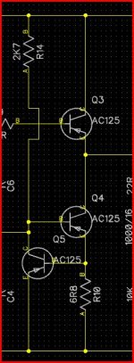
Here's the output section... so lets run through how it works, and how to check it.
You can use PNP or NPN to "prove" this (just swap the supply for NPN), and forget the caps.
So first we connect Q3 and Q4 as shown, together with R10 and nothing else.
In that condition no current flows apart from leakage if using germanium, with silicon it's zero. The volt drop across the 6.8 ohm will be zero... check it.
If that's OK fit Q5 so that the base emitter junction is across R10, and connect it's collector to Q4 base. At this point the current flow is still zero.
[The two transistors Q4 and Q5 form a constant current source limiting the current working as follows.
As the current increases in Q3 and Q4 (which are in "series") the volt drop across R10 must increase.
When it reaches the critical Vbe value (0.17 Ge or 0.7 Si) then Q5 begins to turn on shunting base current away from Q4 so turning it "off" and reducing the current flow.]
So far so good...
so now connect the resistor R14 that supplies base bias to the constant current stage.
At this point the stage should still be drawing no significant current as Q3 base is not supplies with current.
So now to test, connect a 10k or so resistor from Q3 base to the supply.
What should happen is that the current flow should be steady and at a value determined by R10.
Measure the voltage across R10... it will be 0.17 for Ge and around 0.65 for Si. Using ohms law calculate the current. Using 6.8 ohms as shown it will be around 25 milliamp for Ge and if you used Si for Q5 it will be nearly 100 ma... which is to high and will overheat the transistors.
To keep it at 25ma with Si you need to swap R10 for 0.65/0.025 which is 26 ohm or so.
Attachments
Interesting thread. I've probably got some geraniums somewhere. Oddly, I was talking to a septuagenarian colleague yesterday about germanium leakage and he told me that he used to improve the current gain of point contact transistors by heating them and catching them just before runaway. The purpose was to diffuse the lithium further into the substrate, thus thinning the base and increasing current gain.
Interesting thread. I've probably got some geraniums somewhere..
Keep them watered
Hey Mooly!
Alright, it's working much better now! I used a 22R instead of a 27R, so it's still biased a bit high. But now my LM317 isn't getting hot enough to cook an egg and it could be good enough to build on a PCB now!
Thanks so much for your help! By the way, what do you call the output stage?
Kyle
Alright, it's working much better now! I used a 22R instead of a 27R, so it's still biased a bit high. But now my LM317 isn't getting hot enough to cook an egg and it could be good enough to build on a PCB now!
Thanks so much for your help! By the way, what do you call the output stage?
Kyle
Hey Mooly!
Alright, it's working much better now! I used a 22R instead of a 27R, so it's still biased a bit high. But now my LM317 isn't getting hot enough to cook an egg and it could be good enough to build on a PCB now!
Thanks so much for your help! By the way, what do you call the output stage?
Kyle
If you mean R14 ? then that's 2K7 (2700ohms)
The output stage is single ended Class A running into a constant current sink which increases the efficiency to 25% over using just a resistor (12.5%).
Oh no, I meant the 6R8. I thought that would change the bias on it too. Was I supposed to have changed R14 instead of R10? Remember, I am using silicon now. But I'm about to try some germaniums I got today.
Thanks so much for your help!! I'm learning so much from this forum; it's just amazing!
Kyle
Thanks so much for your help!! I'm learning so much from this forum; it's just amazing!
Kyle
- Home
- Amplifiers
- Headphone Systems
- GERMANIUM Single ended Class A Headphone Amp.