Thanks for your feedback
Sorry my bad, changed those caps values to. R2 to 1K and C4 is 100pF.
As far as the transistor go, i had got 2n2222 from local shop, he might also have the mentioned 2N2907 and TIP41 or BD139/140(which i already have). Other options are C945 (and its complement) or BC547 (and its complement) or 2N3904 (and its complement). They are of generic type and feasible for me to get. Other option is to get from Aliexpress. Shipping charges from reputable sites like digikey etc are much higher to my country.
changed it to 0R/jumperThat would not be good...
They're the caps from both regulator's adjust terminal to ground, currently 10uF.
That layout looks much better.
A couple more things: R2 is too high a source impedance for most BJT transistors, especially if there is a pot preceeding it. Something in the 1k to 2k range would be better. And C4 can be lowered to 100pF.
What are you using for Q1, Q2, and Q3?
Sorry my bad, changed those caps values to. R2 to 1K and C4 is 100pF.
As far as the transistor go, i had got 2n2222 from local shop, he might also have the mentioned 2N2907 and TIP41 or BD139/140(which i already have). Other options are C945 (and its complement) or BC547 (and its complement) or 2N3904 (and its complement). They are of generic type and feasible for me to get. Other option is to get from Aliexpress. Shipping charges from reputable sites like digikey etc are much higher to my country.
As far as the transistor go, i had got 2n2222 from local shop, he might also have the mentioned 2N2907 and TIP41 or BD139/140(which i already have). Other options are C945 (and its complement) or BC547 (and its complement) or 2N3904 (and its complement). They are of generic type and feasible for me to get. Other option is to get from Aliexpress.
Yes, I understood that the available parts might be limiited, and may not be genuine. Can you get real 2N5401 locally? It's a good choice for Q2.
The Chinese TIP41C's I have received have all been quite good, and very consistent unit-to-unit.
Checked for 2N5401, they dont have it.Yes, I understood that the available parts might be limiited, and may not be genuine. Can you get real 2N5401 locally? It's a good choice for Q2.
The Chinese TIP41C's I have received have all been quite good, and very consistent unit-to-unit.
Well i was going to make the PCB but then i only had small 100mm x 70mm boards and also my etching pot is small so decided to separate PSU and HP Amp. As its difficult for me to toner transfer bigger sized PCB using iron method.
First made the PSU, but failed. The positive side (LM317) works fine and i can adjust the voltage using the variable resistor.
The negative side gives the same voltage as appearing on input side and the 220R resistor gets hot and discolored / dark. The variable resistor does not make much difference in output voltage. Maybe some mistake on my side, but for the time being will use my old LM7812/7912 PSU for testing.
Also have tried to fit the AMP on 100mm x 70mm PCB. I think i messed up the grounds. If i get time i may build it tomorrow night.
Etched and made the first PCB with parts available to me. Used 10 ohm resistors (instead of 5.1 ohm) as those were the only one available to me. Transistors used are 3904 / 06 and 100% counterfeit TIP41c and mixed capacitors.
I am amazed that it kind of worked partially, i was expecting smoke. left side DC offset was not going below 2.5V, while the right side was going min to 200mv, which i did and tested cheap headphone on right side only. Well it gave sound. I wont try to debug this pcb, i think its not worth the effort. The close placement of components make it difficult to work on it.
Will try to build next one using DC Servo and slightly bigger PCB size.
The Pictures of PSU are also attached. The positive side works. The negative side gives same voltage as input and the 220ohm resistors gets heated.
Bargain alert: A vender on Aliexpress is selling these kits for the next two days for US$14.35 with free shipping. Heckuva deal. These amps are worth the trouble to mod and tweak out.
https://www.aliexpress.com/item/1005001348319476.html
https://www.aliexpress.com/item/1005001348319476.html
Nice work, daemon123!Etched and made the first PCB with parts available to me.
Just an update on the board i built. Well I found the PCB layout of Chinese clone on another Russian site. Etched it, drilled holes and was going to populate it. Wanted to salvage the TIP41C from my previous board. Just as I was disordering the first transistor I found the culprit.

One of the pins of non working side was missed/floating/not soldered. Soldered it this time. Powered it on and it works fine now. No hum or other noticeable noise. The transistor are getting slightly warm (but not hot). But I am unable to get the DC Offset below 175mV.
Also wanted to ask about the three diodes instead of zener diodes. Should they be 4 diodes ?.
Also am amazed that this board worked as i had put mostly salvaged/old parts in it. Only the TIP41 and TO-92 transistor are new.
#70How to reduce its gain ?
https://www.diyaudio.com/community/threads/jlh-headphone-amp.159202/post-2117382
How to reduce its gain ?
Raise R6 (in your original schematic). Gain is R8 / R6 + 1.
I dont have expensive opamps, will 741 / TL-72 work ?
Either will work. I'd probably favor TL072 for servo.
Hi,
Please check the schematic

have added the DC Servo as described here.
Have removed these

Please check if its correct. Also what should be done with un-connected pins of dual opamp. i may use 2x dual opamps.
Also have found these transistors and they are genuine. A933S x 4 and C1740S x 4. Will they work instead of 2N2222 etc..
Their pinouts are different so will have to re-arrange the layout again.
Please check the schematic
have added the DC Servo as described here.
Have removed these
Please check if its correct. Also what should be done with un-connected pins of dual opamp. i may use 2x dual opamps.
Also have found these transistors and they are genuine. A933S x 4 and C1740S x 4. Will they work instead of 2N2222 etc..
Their pinouts are different so will have to re-arrange the layout again.
Here are pics of the working one, with 4 diodes instead of 3.
Using LM7812/7912 based PSU


on start the dc offset is around 70~100mV. Have set the pots
now after 5~15 mins it goes down to 1~3mV offset.
trying to learn how to use RMAA so that i can post some results.
Now to the DC Servo, have tried to make board using the schematic above, if there are some errors then will fix it later, but for the time being made this layout.
Board is cramped size is 100x76mm


Using LM7812/7912 based PSU
on start the dc offset is around 70~100mV. Have set the pots
now after 5~15 mins it goes down to 1~3mV offset.
trying to learn how to use RMAA so that i can post some results.
Now to the DC Servo, have tried to make board using the schematic above, if there are some errors then will fix it later, but for the time being made this layout.
Board is cramped size is 100x76mm
Attachments
Still waiting for someone to confirm the schematic and proper DC Servo part.
in the meanwhile have reduced the gain on my previous built (470R to 2.2K).
Ran RMAA, dont know all the reports but i think its bad.
used about a meter wide two wires from pc to HPA then back to PC line in


Also a few post back, there was version with FET which had DC Servo but with much less components. Will that one work as the 1uf Caps i have are too huge.
in the meanwhile have reduced the gain on my previous built (470R to 2.2K).
Ran RMAA, dont know all the reports but i think its bad.
used about a meter wide two wires from pc to HPA then back to PC line in
Also a few post back, there was version with FET which had DC Servo but with much less components. Will that one work as the 1uf Caps i have are too huge.
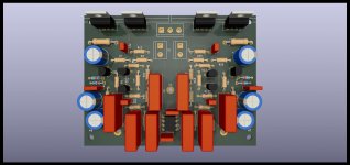
After over a year of working on several different topologies of headphone amps, a tweaked version of this JLH-inspired headphone amp has emerged as one of the top two for hp's of 100 Ohms and up. And it holds up quite well down to 45-ish Ohms at reduced levels. It's time to put it in a suitable case.
This layout is a cap-cooker., with all the large 'lytics in the center of the pcb, surrounded by the hot output devices and regulators on the perimeter. Does an enclosure exist that has has cooling vents optimized for this board?
This layout is a cap-cooker., with all the large 'lytics in the center of the pcb, surrounded by the hot output devices and regulators on the perimeter. Does an enclosure exist that has has cooling vents optimized for this board?

- Home
- Amplifiers
- Headphone Systems
- JLH Headphone Amp