Sorry,you are may be not undestand me. I'm already builded servo dc, like on "shematic to change DC servo connection"
Why do you guys bother with servos and the like. Protect your headphones with 470 uF output cap!
I've built a sort-of-JLH headphone amplifier (single ended PNP input stage with negative feedback to emitter, etc) and I chose to use a capacitor coupled output rather than a DC servo. Mostly because the HPA has a single rail power supply, fed from a DC wall wart made by Triad (this one).
Since it's not inductor loaded (unlike the "MoFo" at the diyAudio store), my single supply amp can't swing its output both above 0V and below 0V. So to keep DC out of the headphones I use an output capacitor. (this one)
Since it's not inductor loaded (unlike the "MoFo" at the diyAudio store), my single supply amp can't swing its output both above 0V and below 0V. So to keep DC out of the headphones I use an output capacitor. (this one)
Yes, use a cap is another alternative: simpler, economical and equally valid, but I think the servo is a *"more elegant" solution.
Of course everyone is free to try the "best" alternative.
*I mean that in this amplifier the servo seems to me more elegant (refined).
I've built a sort-of-JLH headphone amplifier (single ended PNP input stage with negative feedback to emitter, etc) and I chose to use a capacitor coupled output rather than a DC servo. Mostly because the HPA has a single rail power supply, fed from a DC wall wart made by Triad (this one).
Since it's not inductor loaded (unlike the "MoFo" at the diyAudio store), my single supply amp can't swing its output both above 0V and below 0V. So to keep DC out of the headphones I use an output capacitor. (this one)
Dear Mark,
Please share the schematic !
gannaji.
Prototype units of the sort-of-JLH headphone amp, will be shipped to listening volunteers (reviewers) next week. It will take a while for them to do their listening, formulate their opinions, listen some more, and give criticism + feedback. Based on that feedback, I might decide to make schematic changes. Thus I have no final schematic to post today, and I'm certainly not going to post preliminary schematics.
However I am quite sure, these two characteristics definitely will not change: (i) single rail power supply and output coupling capacitor; (ii) single ended PNP input stage with feedback to the emitter à la JLH.
Once it works to everybody's satisfaction, and all design iterations are complete, I will post the whole thing including schematics. But not today.
Hi, so how can we solve this annoying and audible hum?
Measurement setups involving looping a signal over an external amp with all unbalanced connections have this tendency of picking up mains hum due to the inherent ground loop. The amp on its own may be just fine, best confirmed by listening with sensitive headphones.
You were quoting a post that dealt with a measurement artifact. If the problem is plainly audible in the amp, you probably have a PCB with an internal ground loop problem. These have been discussed several times in this thread in the past - maybe you recognize yours on the pictures given, then you could hopefully follow the reworks described.Hi, so how can we solve this annoying and audible hum?
Hi, so how can we solve this annoying and audible hum?
sgrossklass is true, their are some ground issues on the PCB.
I had some issues with ground-like hum in my first build.
It had been solved when I reversed the polarity of 2 100µf capacitors as it's described in post #152 : JLH Headphone Amp
Also, the ground connection of both R&L outputs is a long track accross the PCB as explained in post #~660, that create a ground loop.
To solved it you can use the long wide 0V track of the power supply input as your headphone output ground.
Also, you should take care of the 0V to chassis connection that can make a loop with your audio input sockets.
Last edited:
sgrossklass is true, their are some ground issues on the PCB.
I had some issues with ground-like hum in my first build.
It had been solved when I reversed the polarity of 2 100µf capacitors as it's described in post #152 : JLH Headphone Amp
Also, the ground connection of both R&L outputs is a long track accross the PCB as explained in post #~660, that create a ground loop.
To solved it you can use the long wide 0V track of the power supply input as your headphone output ground.
Also, you should take care of the 0V to chassis connection that can make a loop with your audio input sockets.
thanks for reply, now here is the situation;
i built exaclty the same amp but the (probably) driving to-92 package 2907 transistor at the left side and placed face to face with the 2n2222 is too sensitive to finger touch and i have a dj headphone with a spiral cable, the amp again too sensitive to playing the cable, in both cases, i have an audible and disturbing noise hum
any help will be appreciated
")
Noise hum is gone
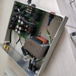
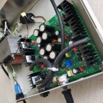
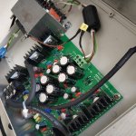
hi bro, i made a star ground to output, potentiometer and heatsink (grounding only one of them is enough)
also i grounded the transformer using a 470pF film cap to limit the current in any bad case,
input and output cables must be shielded cables...
check the pics
i could eliminate the grounding noise hum in a reasonable level and i m satisfied now, try these, it s all about grounding
Thank You ! Thank you !
It works. Now working to get rid of grounding hum and have stereo separation.
hi bro, i made a star ground to output, potentiometer and heatsink (grounding only one of them is enough)
also i grounded the transformer using a 470pF film cap to limit the current in any bad case,
input and output cables must be shielded cables...
check the pics
i could eliminate the grounding noise hum in a reasonable level and i m satisfied now, try these, it s all about grounding
Attachments
Last edited:
Have you tried to separate the transformer?
You have it stuck to the amplifier and this usually causes a lot of problems (HUM).
you re right, it is a classical transformer and magnetic field leak may lead noise, it d be nice to try a toroidal 50VA transformer but i dont have...
the last thing is that my spiral form dj headphone cable can pick long wave radio signals and it is resulted with temporal noise depending it is position, if i insert, e.g, a 10 cm metal lead through the spiral cable, noise is completely gone regardless of cable form and position
I've built a sort-of-JLH headphone amplifier (single ended PNP input stage with negative feedback to emitter, etc) and I chose to use a capacitor coupled output rather than a DC servo. Mostly because the HPA has a single rail power supply, fed from a DC wall wart made by Triad.
Since it's not inductor loaded (unlike the "MoFo" at the diyAudio store), my single supply amp can't swing its output both above 0V and below 0V. So to keep DC out of the headphones I use an output capacitor. (this one)
Dear Mark,
Please share the schematic !
gannaji.
It is here:
Single ended class-A headphone amp using two transistors: T2
AC problem solved
[EDIT 3 MAY]: One test point advised by Miles Campbell in his detailed step by step build/test tutorial in this thread:
"Voltage Regulator output pins WRG - a few millivolts AC"
My problem was that I measured around 25V AC at the regulator output LM7812 & LM7912). Well, it turned out to be some kind "ghost" effect of my cheap multimeter (and the same with another brand cheap multimeter) When measured with a good Fluke it was only a few millivolts AC. So no problem at all and the amp is doing fine service. A warning to all of you building this amp and using cheap multimeters...

- Home
- Amplifiers
- Headphone Systems
- JLH Headphone Amp