Yes, there is also a jumper between this P1-2 to P2-2 trace to GND via the jumper, hence the ground return but also the loops ?the sch shows a gnd symbol attached to the output pin p1-2.
the sch shoiws a gnd symbol attached to the ouput pin p2-2.
The PCB is made to match this.
Instead it connects p1-2 to p2-2
See attached annotated pic.
Attachments
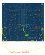
I tried to label all the Ground-Layers on the PCB (see picture). Note the 0 Ohm resistor (wire bridge).
Best regards
Schiller72
Best regards
Schiller72
An externally hosted image should be here but it was not working when we last tested it.
That's a good way of showing it.
And it exposes the problem.
Why are the two outputs sharing a return route?
Why is the return route of such a high impedance (excessively long length)?
Why did the layout designer not just connect EACH output return direct to the power ground? The route would be far shorter and thus lower impedance?
There is one more shorting link tying a second net into the power ground.
That's a good way of showing it.
And it exposes the problem.
Why are the two outputs sharing a return route?
Why is the return route of such a high impedance (excessively long length)?
Why did the layout designer not just connect EACH output return direct to the power ground? The route would be far shorter and thus lower impedance?
There is one more shorting link tying a second net into the power ground.
I'll add on top of that, that if you connect the output to a three pole female headphone jack from P1 and P2 with two wires that share a ground connection at the jack, as most user do with an headphone amp, you add a big ground loop.
That's what my ugly drawing posted on post 662 tried to show with the yellow lines at the bottom.
Yes, and only the thinkers that have got beyond "ground solves everything" will spot that.I'll add on top of that, that if you connect the output to a three pole female headphone jack from P1 and P2 with two wires that share a ground connection at the jack, as most user do with an headphone amp, you add a big ground loop.
That's what my ugly drawing posted on post 662 tried to show with the yellow lines at the bottom.
Headphones are very sensitive. They may replay hum if the field is strong enough. And that happens when high current routes are separated instead of being close coupled.
I clearly stated in an earlier post that there is hum if you use the grounds on each side of the board as outputs grounds.
That was my experience with 2 boards.
Why don't you purchase a board and see(or hear in this case) for yourself?
It's not like it's an expensive board or a issue that can't be easily resolved.
That was my experience with 2 boards.
Why don't you purchase a board and see(or hear in this case) for yourself?
It's not like it's an expensive board or a issue that can't be easily resolved.
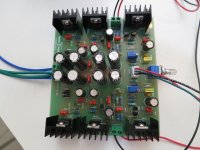
I got my JLH HPA a few days ago. The board is different from the previously posted ones as it has no volume pot and a different layout.Unfortunately I did not have much time to play with it but it works and sounds nice. I could trim the DC offset down to around 1mV but I do not know yet how stable it will be. For extra security I use 4 Nichcon BP 220µF caps at the output. The LMs runs fairly warm but not hot though the TIPs stays fairly cool. I will try to increase the bias a bit in the future but i am not quite sure which resistors I will have to decrease.


help for hum issue and heat
Hello,
I am just close to the end to build this amplifier and was disappointed as I though I should be able to share a trasnformer for both the DAC and this board, but got an horrible hum ground loop issue. Any idea (except of course using separate 220v transfomer ?)
Also I am surprised by the heat or all radiator, is it normal? what is the power needed for this board (did not measure the mA on both +-12V ).
best regards/alain;
You'll have to interrupt the ground loop somewhere. Not too many options for that, try the connection between DAC output and JLH input.Hello,
I am just close to the end to build this amplifier and was disappointed as I though I should be able to share a trasnformer for both the DAC and this board, but got an horrible hum ground loop issue. Any idea (except of course using separate 220v transfomer ?)
I hope your JLH board is not one of those with a integrated ground loop, those also exist (fix mentioned earlier in this thread if memory serves).
It's a Class A amp that runs about 120 mA through the output devices, so that's a good 24 V * 240 mA = 5.76 W dissipated right there, plus a few mA for the rest of the circuit, plus regulator losses... could be about 8 W drawn from the transformer and basically dissipated as heat. Yeah, it'll get a bit warm.Also I am surprised by the heat or all radiator, is it normal? what is the power needed for this board (did not measure the mA on both +-12V ).
Amp not working
[image][/image]
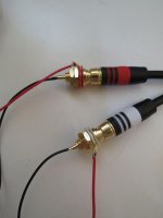
Sorry to ask such a silly question. Have wired the amp and it is not working. The LED is on, what can I do to check the wiring ?
Where do I connect the purple wire ?
Thank you !
[image][/image]
You're quite welcome! Yes, that's the servo board I offer for these amps.
If I were getting an Antek, I would get this one:
AS-1212 - 100VA 12V Transformer - AnTek Products Corp
Hope that helps.
Sorry to ask such a silly question. Have wired the amp and it is not working. The LED is on, what can I do to check the wiring ?
Where do I connect the purple wire ?
Thank you !
Attachments
Last edited:
You have interchanged the inputs and the output.
I knew I would feel silly. The JST goes to the RCA and the screw blocks to the headphone jack.
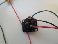
Purple wire is primary ground.
Sorry, Purple and Green for ground ?
That too: one blue wire + one green wire would make CT (ground).
12 - 0 - 12 = Blue - Green + Purple - Blue ?
Sorry, Purple and Green for ground ?
Connect purple to the earth on your main plug.
Last edited:
- Home
- Amplifiers
- Headphone Systems
- JLH Headphone Amp