i was thinking ......
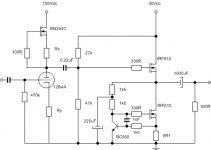
i have 300ohm headphones and i would like to use 12B4A tube at the input of the amplifier together with mosfet follower at the output of the amplifier to drive them....
something like this in attachement.....
ccs is borrowed only for diy purposses from Mr. Pass... ccs in the tube section is plane and simple - did not want to use cascode ccs (it would be probably better) but i don't want to complicate things there to much...
opinions are welcome.....
thanks.
daniel
p.s.
0.22uF coupling cap will be bigger - something like 4.7uF and input coupling cap will be arround 1uF....
Attachments
sparkle said:i was thinking ......
i have 300ohm headphones and i would like to use 12B4A tube at the input of the amplifier together with mosfet follower at the output of the amplifier to drive them....
something like this in attachement.....
ccs is borrowed only for diy purposses from Mr. Pass... ccs in the tube section is plane and simple - did not want to use cascode ccs (it would be probably better) but i don't want to complicate things there to much...
opinions are welcome.....
thanks.
daniel
p.s.
0.22uF coupling cap will be bigger - something like 4.7uF and input coupling cap will be arround 1uF....
input cap ?
why?
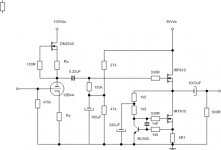
It may be that I'm just being overly cautious, but as this is a headphone amp, I think you have to make an extra effort to reduce power supply hum. You might want to consider not connecting the 27k/47k bias network directly to the signal line. I would put a capacitor at the 27k/47k juncture and then join this now very stable DC bias voltage to the signal line through a 100k resistor.
Jim
Jim
THANKS GUYS
Zen Mod - you are right - i really don't need that input cap - i thought to put it there only "just in case".... but i really do not need it...
JimT - thanks for the idea.... nice.... you have something like this in Your mind - right
Zen Mod - you are right - i really don't need that input cap - i thought to put it there only "just in case".... but i really do not need it...
JimT - thanks for the idea.... nice.... you have something like this in Your mind - right
Attachments
i will do that - it is a slow process of building it (not much time to do that) but it is going forward....
i am thinking if i need that 10uF cap... it seems to me it is big and that i can got with 1uF with no problem - but also i have seen some not so rectangular outputs when trying the schematic with 20Hz step signal at the input.... with 10uF - everything is fine - with 1uF the signal is not very good when using 20Hz... so i am a bit worried to use 1uF only ...
what do you think guys ... should i stick to 1uF between tube and mosfet stage, or should i go for 10uF which is looking far better when using 20Hz step input into the tube???
Re: THANKS GUYS
Yes thats it.
I think the 12B4 has a gain of about 6. If thats the case, you will need more volts on the mosfet section to be able to handle all that the tube sends it. On the other hand, unless your headphones are very inefficient, you will not need all of the gain of the tube so things should be fine. My 130 ohm Sennheiser 595's are almost painfully loud with a zero gain headphone amp.
ZenMod can set you right if I have made a mistake.
Jim
sparkle said:Zen Mod - you are right - i really don't need that input cap - i thought to put it there only "just in case".... but i really do not need it...
JimT - thanks for the idea.... nice.... you have something like this in Your mind - right
Yes thats it.
I think the 12B4 has a gain of about 6. If thats the case, you will need more volts on the mosfet section to be able to handle all that the tube sends it. On the other hand, unless your headphones are very inefficient, you will not need all of the gain of the tube so things should be fine. My 130 ohm Sennheiser 595's are almost painfully loud with a zero gain headphone amp.
ZenMod can set you right if I have made a mistake.
Jim
the voltage on the follower is not fixed - i will decide about it the moment i find some suitable xformer in my junkbox....
my intention is to build everything out of the box first and see if i need the tube or not... and than to decide what to do... when i see how much gain i will need and if the amplifier is sounding good, than i will put it inside the box.....
my intention is to build everything out of the box first and see if i need the tube or not... and than to decide what to do... when i see how much gain i will need and if the amplifier is sounding good, than i will put it inside the box.....
 Weird. Yesterday I was looking at that tube yesterday and 6sn7gt/12sn7gt for a hybrid headphone amp. Lo and behold...
Sonidos
believe me - i am also very interested to see how my project will turn out....
unfortuantelly you will have to wait a bit because i do not have to much free time and also i am going on a BIG vacation so you can imagine how slow it will go.... BUT, i am determined to make it... i am happy to use tubes in this project (because i am a huge fan of tubes in a line stage).... so it will be done - hopefully my amplifier will work and my heads will be happy with it.....
i have MbQuart QP400....
don't worry - i will keep everybody up to date....
the only problem i can see here is my time to do it....
Sparkle,
Have a nice LOOONG vacation. 18 years ago when I was a younger man, I tutored a teenage boy whose grandmother was from Croatia. He went on vacation with his mother and brought back several photos of the coast. Very nice.
I'm in no hurry either as I'm rebuilding my Adcom amp plus building the PASS F5 and B1.
But yeah, I keep reading about how great tubes sound for a headphone amp. I've already bought some 12AU7s and 6AS7GTs (but man are they current eaters). So I'm going to do some experimenting during the summer and fall this year.
actually - i am going on a vacation in USA, Dallas ....
yes - croatian coast is very nice... the best places i like the most are arround Makarska and Dubrovnik....
sorry for the offtopic...
6AS7GT is a huge tube that is not actually at their best in line amps.... the main problem when making the line preamp is to keep the gain low (if you do not want to implement feedback or multiple stages)... i like it simple (one stage) with no feedback..... for this, during several years of searching, i found 12B4A to be the best to my ears - but only when using ccs in the anode.....
that is why i want to use it here also... i like that tube when working with bipolar transistors at the output of the amplifier... i never tried it in mosfet follower, but heard that it should be nice also....
so this will be interesting for me too....
you can try to build Aikido input stage before the mos follower (from Mr. Broskie)... i have found out that it is very nice sounding - and you can use your 12AU7 (very nice sounding tube also) in the input part of the Aikido - this way you will have (after the input of the Aikido, before the output part of the Aikido) half of the gain of the mu of the input tube... if you know what i mean....
....
this would also be one of my choices but i do not have enough space to put it....
....yes - croatian coast is very nice... the best places i like the most are arround Makarska and Dubrovnik....
sorry for the offtopic...
6AS7GT is a huge tube that is not actually at their best in line amps.... the main problem when making the line preamp is to keep the gain low (if you do not want to implement feedback or multiple stages)... i like it simple (one stage) with no feedback..... for this, during several years of searching, i found 12B4A to be the best to my ears - but only when using ccs in the anode.....
that is why i want to use it here also... i like that tube when working with bipolar transistors at the output of the amplifier... i never tried it in mosfet follower, but heard that it should be nice also....
so this will be interesting for me too....
you can try to build Aikido input stage before the mos follower (from Mr. Broskie)... i have found out that it is very nice sounding - and you can use your 12AU7 (very nice sounding tube also) in the input part of the Aikido - this way you will have (after the input of the Aikido, before the output part of the Aikido) half of the gain of the mu of the input tube... if you know what i mean....
....
this would also be one of my choices but i do not have enough space to put it....
You might find my drawings of another thread to be relevant.
Tricks to get a bit more from your current sources and triode.
http://www.diyaudio.com/forums/showthread.php?s=&threadid=140114
Tricks to get a bit more from your current sources and triode.
http://www.diyaudio.com/forums/showthread.php?s=&threadid=140114
o.k. guys - long time no seen here
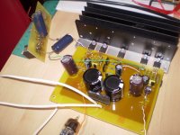
i made the circuit according to the schematic in the post no.4...
first i made the output buffer and i was listening the music on it... it was o.k.... not out of this world but also not bad....
i suspect that the sound quality was not so good because i was having a buffer stage with low impedance as a load on a Shigaclone CD player... and Shigaclone is not capable of driving anything problematic... so i was not worried....
today i made a tube part of the schematic - checked everything and after checking turned it on....
everything seemed to be fine - DN2540 was set to drive the tube with 20mA of plate current - fine with the tube and fine with me... the plate voltage on the tube was 106Vdc - also fine with me ... the coupling capacitor was 1uF instead of 0.22uF like in the noted schematic...
when i turned on the headphones - i was for a surprise.....
the sound was lacking bas completely... also a part of the middle was not present.....
so i decided to put a bigger coupling capacitor - i found some 100uF electrolythic cap's and put them as coupling cap's ... it was better - but still i am lacking some of the bass - and it's not small... i have bas now but not nearly enough....
so, i am asking you guys - can somebody tell me if this is normal ?? what should i do??.... to change the tube driver for the output buffer??? or just to simply put a JFET front end or something... because now, i am stuck with the output buffer that i would not like to change - the only thing i can change is the front end....
any suggestions...???
thnx for every effort ....
regards
- Status
- This old topic is closed. If you want to reopen this topic, contact a moderator using the "Report Post" button.
- Home
- Amplifiers
- Headphone Systems
- headphone amplifier = tube + mosfet