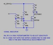
sweet, but check it out. i'm a total noob so is that arrow on the bottom a ground? since this gonna be portable and isn't actually gonna be able to touch a ground, would that be the negative terminal on the 9 volt battery? do I also connect the ground from my headphone amp to the same place? 
I have 2N2222 transistors. how would i modify this to use that part?
I have 2N2222 transistors. how would i modify this to use that part?
you could use the 2N2222 transistors, but your bias voltage will be about 0.7V instead of between 3 and 5V, so you will want to replace the 100k resistor (R3) with a 10k or 20k. R1 would connect to the collector, ground to the emitter and the junction of R2,R3 to the base.
on a 2n2222 if you look at the transistor with the flat (numbered) side toward you and the wires pointing down, the wires are from left to right Emitter Base Collector. -28db is about 2millivolts, not sure if a 2N2222 will have enough gain by itself to be a good indicator driver. maybe the MOSFET would suffer the same problem. you might need to make the two 2N2222's into a darlington where you connect the collectors together, connect the input transistor emitter to the base of the output transistor, and the emitter of the output transistor goes to ground. this creates a compound transistor known as a darlington. the gain of the transistor is the gain of the first transistor multiplied by the second one, the base is the base of the input transistor the emitter is the emitter of the output transistor and the collector is the two collectors tied together the bias will now need to be 1.4 volts.
on a 2n2222 if you look at the transistor with the flat (numbered) side toward you and the wires pointing down, the wires are from left to right Emitter Base Collector. -28db is about 2millivolts, not sure if a 2N2222 will have enough gain by itself to be a good indicator driver. maybe the MOSFET would suffer the same problem. you might need to make the two 2N2222's into a darlington where you connect the collectors together, connect the input transistor emitter to the base of the output transistor, and the emitter of the output transistor goes to ground. this creates a compound transistor known as a darlington. the gain of the transistor is the gain of the first transistor multiplied by the second one, the base is the base of the input transistor the emitter is the emitter of the output transistor and the collector is the two collectors tied together the bias will now need to be 1.4 volts.
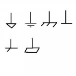
yes. ground symbols are somewhat iconic (they somewhat resemble what they are, or were when the symbol was invented) here are several different symbols for ground some are for "EARTH" ground some are for chassis ground or "common" you may even see more than one used in a schematic or the same symbol but a letter like "C" or "E" or "G" or other letters like "A" for analog and "D" for digital.
a couple of the symbols are iconic of a stake driven into the dirt, a couple are iconic of attachment to a metal frame (once in a while you will see "frame ground" referred to), one is iconic of attachment to a busbar..... you get the picture? (pun intended)
a couple of the symbols are iconic of a stake driven into the dirt, a couple are iconic of attachment to a metal frame (once in a while you will see "frame ground" referred to), one is iconic of attachment to a busbar..... you get the picture? (pun intended)
Attachments
Ok, i set up the circuit like you said with the 2n2222, but I'm having a rough time getting it biased with fixed resisters (i don't have any pots and i need this thing to be as robust and compact as possible). am I right in assuming that the total voltage drop across R2 and R3 should be 9v and I'm looking to get around .7 across r3:
bias voltage / R2 voltage drop = R3/R2 = .7v/8.3v = 10kOhm/R2
R2= 10kOhm*8.3v/.7v = 83kOhm/.7 = 119kOhm
does that look right? my circuit seems to be intermittently validating it, but it just died, so i wonder if i blew another transistor.
bias voltage / R2 voltage drop = R3/R2 = .7v/8.3v = 10kOhm/R2
R2= 10kOhm*8.3v/.7v = 83kOhm/.7 = 119kOhm
does that look right? my circuit seems to be intermittently validating it, but it just died, so i wonder if i blew another transistor.
just an "off the top of my head" calculation. make R2 30k, and R3 2.4k. the reason for the high resistor values with the mosfet, is that the gate was being biased by voltage only. a bipolar needs a bias current.
with the 1k resistor in series with the LED, and with other values shown in the drawing or suggested in this message, you shouldn't be burning transistors out, especially with a 9V source. the transistor ideally should be biased just at it's conduction threshold so that adding signal will turn it on
with the 1k resistor in series with the LED, and with other values shown in the drawing or suggested in this message, you shouldn't be burning transistors out, especially with a 9V source. the transistor ideally should be biased just at it's conduction threshold so that adding signal will turn it on
There are 2 main types of level detectors.
* peak
* average
a peak detector will make LED light as soon as only one short signal reaches a certain voltage
as such sginal peak can be very short, the human eye will not be able to see it
* so peak detectors needs some storage
usually the short peak will load one rechargable capacitor
and fed by the capacitor the LED will light long enough for human eye to see
average level detector
this will light when the average of the music reaches a certain level
* by simply adjusting one potentiometer
we can adjust so that eye can see the LED light at one average level
(even if the peaks are not visible)
what i'm trying to do with it is to use it as a visual metronome. I am gonna have my accompaniment music on the left channel and the right channel will feed the LED circuit with a click or high hat. this way i can I can have the backing music drop out and come back in and I will still be in synch.
ok, i set R2 to 30k and slowly boosted R3 from 2.4k, but it appears that it isn't until 8.8k that it lights up and at 7.6k it goes back off (sans audio). When I feed in the audio at that bias it does show the signal flickering, but it's really faint and I have R5 at 100k and R4 at 0. I have to figure out how to get it blazin' so I can see it clearly from a couple meters away. I also need it to sense a lower threshold of sound.
this is because of our eye can not catch 'flickering' very well
we can use the method I described.
1. at a certain level a transistor gives a short current pulse, spike
2. this spike will charge one capacitor
3. the capacitor will only slowly discharge, while feeding another transistor
4. that will keep LED ON until voltage across cap is low again
we can say the cap is a memory, a storage
that makes the LED have a delay, before turn off
would a capacitor add a delay to the beginning of the pulse--the light turning on? timing is critical.
couldn't I also get the same length from having the circuit tuned to engage at a very low threshold and using a longer decaying sound for the pulse...i.e. a slightly loose high hat?
would it help if I rectified the audio signal?
couldn't I also get the same length from having the circuit tuned to engage at a very low threshold and using a longer decaying sound for the pulse...i.e. a slightly loose high hat?
would it help if I rectified the audio signal?
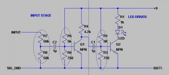
if you were to add another similar circuit before the capacitor, you could get a lot more gain. the circuit below should be workable. the resistor dividers shown in dotted circles will need to be adjusted experimentally as you did with the first circuit. actually you already have half of it figured out, you just need to remove R4 and R5 and substitute everything to the left of the dotted line. you could probably do well to begin with the new R5/R6 divider with the same values you have for R2/R3. you're right about adding a dwell time capacitor, it would also introduce the same delay lighting the LED as you would have added delay in the LED going out. since you are definitely looking at using this as a "metronome", you might find it best to keep both transistors biased just below cutoff as you already do with the circuit you have now.
Attachments
cool, man. thanks for the sketch.
i confirmed your 2.4k in my voltage calculations. any idea why it took such a larger value? I'd like to try to narrow down the number of permutations using some math. what kind of current do I want to see across the bases? would boosting it help the brightness of the signal? so the darlington is not the answer here?
I looked at rectifying circuits and it looks like I couldn't do it without loosing gain, so that's a trade-off. I'm beginning to see why amplifiers are still so expensive.
a darlington might work, since we're presetting the bias, and it would reduce the parts count, but you have more flexibility with the two transistor circuit. you can add more stuff after the input stage, like low pass filtering, etc..., because you have boosted the signal enough to do more things with it.
not really. it's probably a bit trickier to set 2 bias strings. the darlington would probably allow you to use higher value resistors, which would reduce the loading your circuit puts on the mp3 player output. your bias setting will be 1.4 volts or so rather than the 0.7 for each transistor, but the current required to maintain conduction will be much smaller, so you can use a bias etting string totalling 100k rafher than two that total 10k each.
- Status
- This old topic is closed. If you want to reopen this topic, contact a moderator using the "Report Post" button.
- Home
- Amplifiers
- Headphone Systems
- simplest LED circuit driven by mp3 player headphone amp